For applications in many automotive environments and ECUs, the voltage provided by the battery and generator will be insufficient and must first be converted to the correct voltage level. A DC/DC switching voltage regulator and a linear regulator are typically used to achieve this goal. This article will focus on the discussion of switched regulators because linear schemes cannot produce output voltages above the input voltage.
This article refers to the address: http://
The most commonly used topology is the buck converter (Figure 1), which requires only a single inductor and a set of diodes and switches to achieve one of the simplest and most cost-effective options in a switched DC/DC solution. The only downside, however, is that this method only produces an output voltage that is lower than the input voltage. If the output voltage needs to be higher than the input voltage, you can use a "reverse" topology or boost converter (Figure 2). The components required for this topology are similar, but can produce an output voltage that is higher than the input voltage.
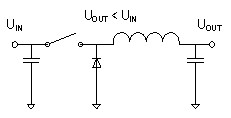
Figure 1: Basic Buck Converter
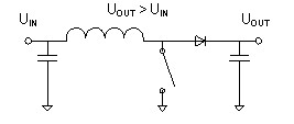
Figure 2: Basic Boost Converter
Since the voltage of the automotive grid voltage varies considerably (down to 3.5V at startup and up to 45V during clamp load dump), in some ECU applications, the input and output voltages must cross each other. Situation. During start-up (starting the engine), sudden power loss is never allowed, especially for powertrain applications or some navigation and infotainment systems. This problem can be solved by using a flyback converter or SEPIC topology, but the required transformer type The extra cost and space of the inductor is relatively unattractive for the customer.
Even if the input voltage crosses the output voltage value, the buck-boost topology provides a stable output voltage and a simple design that uses only a single coil, combining the buck and boost converters in the same topology. Seamless transition between two different modes produces a stable, uninterrupted output voltage across all input voltage conditions.
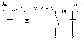
Figure 3: Asynchronous Buck-Boost Converter
Combining two different topologies here, the asynchronous buck-boost converter requires two sets of switches and diodes (Figure 3) compared to a simple buck or boost mode using a set of switches and diodes. To improve overall performance, a diode can be used instead of a diode. The current topology combined with the inductor looks similar to a complete H-bridge (Figure 4).
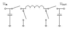
Figure 4 switch replaces the diode
The general functionality of these devices can be subdivided into three modes of operation:
1. The buck mode when the input voltage is higher than the output voltage
2. The boost mode of the input voltage is lower than the output voltage
3. Transfer of input voltage in the output voltage range
Buck mode operation
In buck mode operation, the input voltage must be higher than the output voltage and is functionally similar to the basic buck topology. In buck mode, the converter's boost switches (B1 and B2) do not switch, and the B1 switch must be off, allowing current to flow from the inductor to the output capacitor. The B2 switch must be turned on to avoid shorting the output to ground (GND).
When switching to "on time", the A1 switch is turned off to charge the inductor (Figure 5). During this cycle, current flows from the input through the A1 switch, the coil, and the B1 switch, and into the output capacitor.
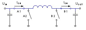
Figure 5: Buck converter current flow in the conduction phase
During the second phase of the cycle (off time), the A1 switch will turn on and the A2 switch will turn off (Figure 6). The magnetizing coil forces current from GND through the A2 switch, coil, B1 switch, and then into the output capacitor (also known as the flywheel).
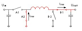
Figure 6: Buck converter current flow in the flywheel phase
In the asynchronous topology, the A2 switch is replaced by a diode as a passive flywheel assembly. This reduces the number of drivers and field effect transistors (FETs) used, but also reduces the performance of the converter. The switching duty cycle in this operation is based on the input-to-output voltage ratio shown in Equation 1.
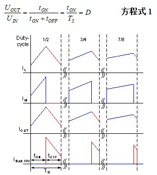
Figure 7: Current waveform boost mode operation during buck switching phase
In boost mode operation, the input voltage must be lower than the output voltage and the device operates with a basic boost topology. The converter's buck switches (A1 and A2) do not switch in this mode. A1 must be turned off to allow current to flow from the input to the inductor; A2 must be turned on to avoid shorting the input to GND.
When switching to "on time", the B2 switch is turned off to charge the inductor (Figure 8). During this cycle, current flows from the input through the A1 switch, the coil, and the B2 switch, and enters GND.
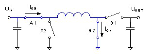
Figure 8: Boost converter current flow in the conduction phase
During the second phase of the cycle (off time), the B2 switch will turn on and the B1 switch will turn off (Figure 9). The magnetizing coil forces current from the input through the A1 switch, coil, B1 switch, and then into the output capacitor.
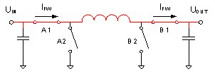
Figure 9: Boost converter current flow in the flywheel phase
In the asynchronous topology, the B1 switch is replaced by a diode as a passive flywheel assembly. The final result is the same as that described in "Buck Mode Operation". The switching duty cycle in this operation is based on the input-to-output voltage ratio (Equation 2).
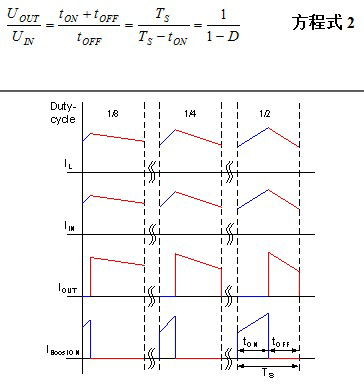
Figure 10: Current waveform during the boost switching phase
Transfer operation
If the input and output voltages are very close, using a basic buck or boost mode alone, the stable output voltage controlled by the closed loop cannot be maintained. One possible approach is to switch between different modes at a specific input voltage level (for stability, the voltage threshold has hysteresis). Another approach may be to alternately switch the frequency cycle to operate the buck and boost modes together to ensure a stable output voltage and good transient response.
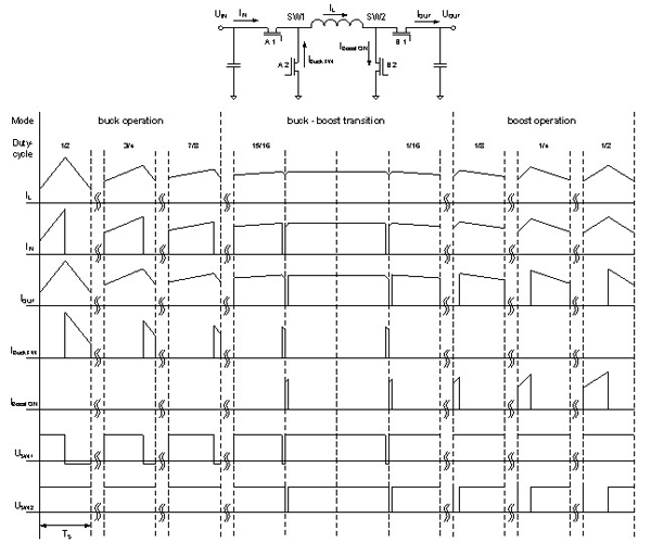
Figure 11: Current and voltage waveforms in different operating phases and modes
in conclusion
Many products can help customers solve the challenges of wide extension of the 12V grid voltage range, such as cold start conditions, load dump, or battery drain. For example, TI's TPIC74100 fully integrated 5V 1A buck-boost converter maintains a stable output voltage and does not require expensive and bulky transformer-type inductors, thus ensuring that the application is fully implemented under various battery voltage conditions. operating.
modern led Crystal Floor Lamp , main material is stainless steel and Top K9 crystals. The light source is LED SMD or led spot light. There are many different patterns and designs for customer to choose. We can make light according to customers' requirments. The use of minimalist design style is more vitality, but also more in line with modern fashion and seeking quiet, the pursuit of nature. Generally arranged in the living room and rest area, with the sofa, coffee table with the use of the room to meet the local lighting and decorative decoration of the family environment needs.
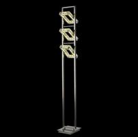
Modern Crystal Floor Lamp,Crystal Floor Lamp,Modern Floor Lamps,Crystal Chandelier Floor Lamp
Laidi(Zhongshan) Lighting Co.,Ltd. , http://www.idealightgroup.com