Commonly some electronic class enthusiasts DIY Joule thief circuit.
Such
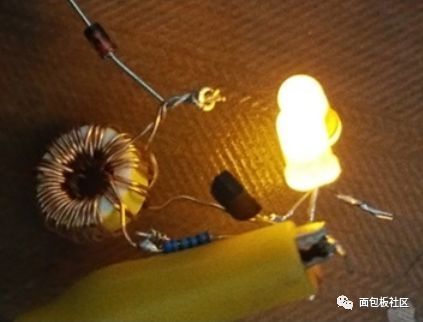
Such 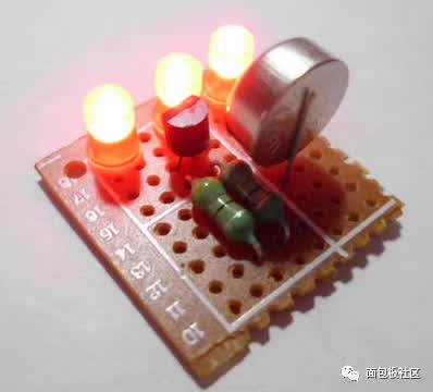
There is such a
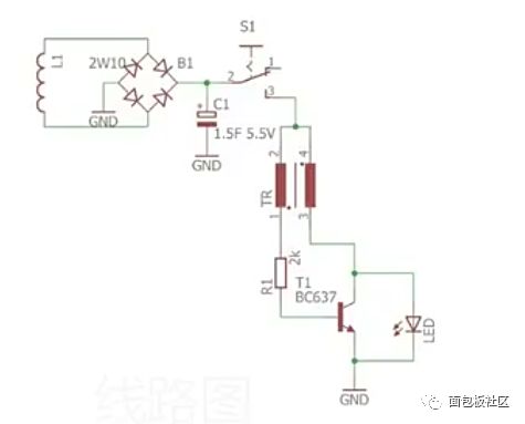
The Joule Thief circuit is a simple self-oscillating boost circuit that requires only three components: a triode, a resistor, and an inductor to achieve boost, low cost, and easy to manufacture.
It can drain all the energy on a used dry battery, even those that are already considered dead in other circuits. When making a Joule thief circuit, be sure to pay attention to the opposite direction of the two inductors. Usually 1.5V dry battery will have a voltage of about 1.1V after use, indicating that there is energy in the battery at this time, but the internal resistance is very large, the output current is very weak, it is unable to drive the general circuit, and it is impossible to Bright LED. The Joule thief circuit can generate a high-frequency pulse voltage through the magnetic induction coil to turn on the LED. By adjusting the appropriate parameters, the battery voltage can be increased by 10-100 times.
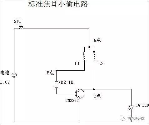
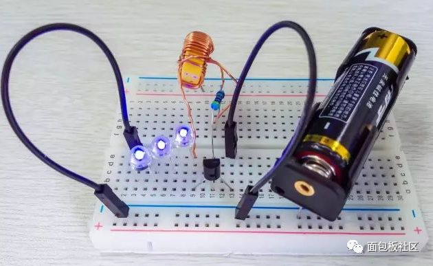
The following analysis of the focus ear thief circuit is easy to understand.
Joule thief full explanation
Light up an LED:
We know that the LED operating voltage is usually 1.7 ~ 3V, that is, to light the LED we need a voltage higher than 1.7V.
So the easiest way to light up the LED is - as shown:
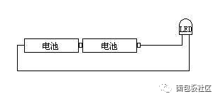
The LEDs are illuminated by a voltage of more than 1.7V. This is a very simple job.
Now let's look at the picture below:
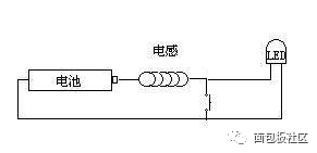
Here, we replaced a battery with an inductor and added a switch.
At this time, the LED cannot be lit because its voltage is only 1.5V supplied by a battery.
When we press the switch, the battery only supplies power to the inductor, and the current forms a magnetic field on the inductor.
This process is also called battery-to-inductance energy.
When the switch is released, the voltage on the inductor is superimposed on the battery to discharge the LED, which is higher than 1.7V, thus illuminating the LED.
Here the inductor acts as a battery. Unlike ordinary batteries, the energy of the inductor is dependent on the battery.
The battery is required to continuously charge the inductor and then release it to the outside.
We can't keep pressing that switch all the time, and let us rely on us manually, and its working frequency is very low.
Then the LED flashes off, and it is even hard to see that the LED is shining.
At this point we took a triode as an automatic switch instead of our manual switch.
The circuit edge evolves to:
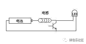
Now we can control the conduction or termination of the triode by simply giving a signal to the base of the triode.
Just by periodically giving the base signal, the triode acts as an automatic switch.
Can complete the conversion of the battery load from the inductor and the LED.
When the inductor becomes a load, the battery is energized by the inductor, (the transistor is turned on), and when the LED becomes a load, the (triode cut-off) inductor releases energy.
Look at the picture below:

Here we add a set of feedback coils to provide a trigger signal to the triode.
When there is current on the inductor when the inductor is energized, the induction coil can provide a trigger signal for the triode to turn on the transistor.
When the inductor is energized, a magnetic field is formed on the inductor, and an induced electromotive force is also generated. This electromotive force prevents current from flowing through the inductor.
This is the lack of sufficient induced current on the induction coil to maintain the triode conduction, at which point the triode is turned off.
As a result, the triode cooperates with the inductor to form a conduction-to-off-conduction-continuous cycle.
It is equivalent to the switch in the above description, and it is continuously on and off.
So in the end, we have to protect the triode to avoid the breakdown of the base of the triode. This forms the circuit of the Joule Thief:
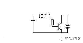
Now we should understand the general knowledge of the Joule Thief, and thus know what role each component plays in making a Joule Thief.
Then understand that as long as it is a triode, it can be used to make Joule thieves, as long as this triode has the ability to be turned on.
Magnification, operating frequency can be ignored.
As long as the signal can be used to maintain the conduction and cut-off of the triode, even the thyristor, the Darlington composite tube can be competent.
The things to note here are:
1. The inductor requires a high magnetic permeability because the inductor provides energy to the outside and relies entirely on the magnetic energy it stores to convert it into electrical energy. It is known that the greater the magnetic energy that the inductor can store when energized, the higher the energy supplied.
2. The Joule thief provides pulsed direct current to the outside, not alternating current.
3. Any electronic circuit consumes power, and the Joule thief consumes only a slight loss in inductance and a little energy to turn on the transistor.
This is also the magic of the Joule Thief, if we make a single tube self-oscillation, forming an alternating current, and then boosted by the transformer.
It also boosts the voltage, but the energy consumed by the electronic circuit in this process is much larger than that of the Joule thief.
So the concept of Joule thief should be explained, and the rest is off topic.
As we saw in the first picture, if we have enough batteries, then we don't need any Joule thieves.
If we have enough energy, then we can light the LEDs at will, and the Joule Thief is meaningless.
So what do we mean by making a Joule thief? This is yet to be studied.
Now we just use the remaining energy in the used battery to do the final work for us to light the LED.
This is what we ask Joule Thief to have a very low starting voltage.
Generally, the minimum operating voltage of the NPN type transistor is 0.7V, and the PNP type transistor is 0.3V.
Then we know what kind of triode should be used, and it is more suitable to drain poor batteries.
5000Puffs Disposable Vape,E-Cigarette R&M 5000Puffs,5000Puffs Vape Pod,5000Puffs E-Cigarette Pod Device
Shenzhen Uscool Technology Co., Ltd , https://www.uscoolvape.com