Dazzling advertising lights can be seen everywhere, it will be beautiful and charming in the night of the city, the merchant has been unable to leave the advertising lanterns as a very effective propaganda weapon. Advertising lantern control for a variety of patterns can be achieved with inexpensive integrated chips. In this paper, the 8-channel lantern control circuit is designed by using the most commonly used 555 timer and 74LS series devices. The design circuit is simulated and verified based on Multis-im software. The PCB circuit of 8-channel lantern control circuit is designed based on protel99. 8-way lantern control.
1 system design
1.1 System function The block diagram of the 8-way lantern control system is shown in Figure 1. The clock generation circuit generates a clock signal having a frequency of about 1 Hz, and the output signal of the clock generation circuit is used as a CP pulse of the address generator, and the control address generator generates an address signal that is automatically incremented by one and cyclically changed. The address generated by the address generator controls the time-division electronic switch to turn on and off in a time-sharing manner, and the 8-channel lanterns are sequentially illuminated in time, and each lamp is continuously lit for 1 s, and is cycled every 8 s. The visual effect of the advertising lantern is controlled by the on/off switch of the time switch, and the on/off cycle of the time switch in the system is completely controlled by the clock generation circuit.
This article refers to the address: http://

1.2 chip function introduction 1) 555 timer 555 timer is an 8-pin integrated device, its working principle is: the output voltage has only two states: high level, low level. Under the condition that the R terminal of the reset terminal of the 555 timer is low, regardless of the threshold input terminal TH and the trigger input terminal ![]() What value is taken, the output terminal OUT outputs a low level, and the discharge port D is connected to the ground. When the reset terminal R is at a high level, if the threshold voltage is TH>2Vcc/3, and the trigger voltage
What value is taken, the output terminal OUT outputs a low level, and the discharge port D is connected to the ground. When the reset terminal R is at a high level, if the threshold voltage is TH>2Vcc/3, and the trigger voltage ![]() The output terminal OUT outputs a low level, and the discharge port D is connected to the ground; if the threshold voltage is TH<2Vcc/3, and the trigger voltage
The output terminal OUT outputs a low level, and the discharge port D is connected to the ground; if the threshold voltage is TH<2Vcc/3, and the trigger voltage ![]() , the output terminal 0UT and the discharge port D remain unchanged: as long as the trigger voltage
, the output terminal 0UT and the discharge port D remain unchanged: as long as the trigger voltage ![]() At the output terminal OUT outputs a high level, and the discharge port D is disconnected from the ground.
At the output terminal OUT outputs a high level, and the discharge port D is disconnected from the ground.
2) Hexadecimal counter 74LS161 74LSl61 is a 16-pin device, its function is: 74LS16l has clear, count, set function, when clearing the end ![]() When it is low, the output terminals Q0, Q1, Q2, Q3 output low level; when clearing the end
When it is low, the output terminals Q0, Q1, Q2, Q3 output low level; when clearing the end ![]() Is high, and the number is set
Is high, and the number is set ![]() When it is low, when the rising edge of the CP pulse comes, the set function is completed, that is, Q0=D0, Q1=D1, Q2=D2, and Q3=D3. When clearing the end
When it is low, when the rising edge of the CP pulse comes, the set function is completed, that is, Q0=D0, Q1=D1, Q2=D2, and Q3=D3. When clearing the end ![]() Number terminal
Number terminal ![]() When the enable terminal CTP and CTT are both high, the counting function of the CP pulse is completed.
When the enable terminal CTP and CTT are both high, the counting function of the CP pulse is completed.
3) 3-wire-8-line decoder 74LSl38 74LSl38 is a 16-pin integrated device whose function is: when the enable terminal G1 is high, ![]() When it is low level, the 74LS138 has a decoding function. At this time, when the input signals of the input terminals C, B, and A are sequentially changed from 000 to 111, the output terminals Y0, Y1, Y2, Y3, Y4, Y5, Y6, and Y7 The low level in the output is shifted from Y0 to Y7.
When it is low level, the 74LS138 has a decoding function. At this time, when the input signals of the input terminals C, B, and A are sequentially changed from 000 to 111, the output terminals Y0, Y1, Y2, Y3, Y4, Y5, Y6, and Y7 The low level in the output is shifted from Y0 to Y7.
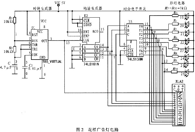
1.3 Circuit Design and Simulation 1) Lantern Circuit Design The lantern circuit consists of a color LED and a 1 kΩ current limiting resistor, for a total of 8 channels. Considering the realization characteristics of the time-division electronic switching circuit, the eight-way LED circuit is designed as a common anode connection mode, that is, the anodes of the eight LEDs are commonly connected to a 5 V DC voltage source. The cathodes are respectively connected to the 8-way time-divided electronic switch through the resistor, and the 8-way lantern wheel is controlled to be broken by the time-division electronic switch. The lantern circuit is shown in Figure 2.

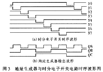
2) Time-division electronic switch is designed in the system. The function of the time-division electronic switch is to automatically control the 8-way lantern circuit to turn on the power. By using the decoding characteristics of 74LSl38, as long as its input address CBA can be periodically changed from 000→00l→001→010→011→100→101→110→111, 74LSl38 can complete the time-division electronic switch function required by the system. The time-division electronic switch circuit of the design is shown in the figure of Figure 2, and the timing of the 8-way switch being turned on is shown in Figure 3.

3) Address generator design The function of the address generator is to automatically generate the address of the periodic automatic plus l change, and control the time-division electronic switch circuit to rotate according to the system requirements. With 74LSl61, the hexadecimal count is designed, and its output signal can be automatically added with a change of 1 periodically. The third output is used to provide the changed address for the time-division electronic switch. The address generator circuit is shown in Figure 2, and its lower three-bit output signal waveform is shown in Figure 3.
4) Clock Generator The clock generator circuit provides a clock signal to the system, which provides a clock pulse for the address generator. It controls the rhythm of the entire system and controls the cycle speed of the lantern. Since the system operation does not require high clock frequency stability, the multi-vibrator designed by the 555 timer can meet the system clock requirement. Considering the visual effect requirements of the advertising lantern, the oscillation frequency of the clock generation oscillator is designed to be 1 Hz. The clock generator circuit is shown in Figure 2.
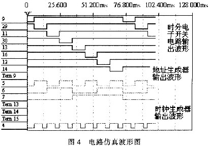
2 circuit simulation design of the pattern advertising light circuit shown in Figure 2. The output of the clock generator, address generator and time-division electronic switch circuit is connected to the logic analyzer. The circuit simulation results are shown in Figure 4. (For quick and convenient simulation, Figure 4 is at a system clock frequency of 10 Hz. The simulation results do not affect the verification of system functions). As can be seen from the simulation waveform, at the rising edge of each pulse of the clock generator output signal, the address generator output address changes once, and at the same time, the time-division electronic switch has one way to turn on; under the action of the clock pulse, the output of the address generator The periodicity of the waveform is from 000→001→010→011→100→10l→110→111, and the order of the time-division electronic switch is turned on (low level) is Y0→Y1→Y2→Y3→Y4→Y5→Y6→Y7 The simulation results are completely consistent with the theoretical analysis results and system functional requirements.

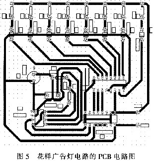
3 PCB circuit design and circuit assembly Complete the circuit design, and verify that the circuit function is correct after simulation, design the printed circuit based on Protel99, as shown in Figure 5. Through assembly and debugging, the circuit function is completely normal.

4 Conclusions The 8-channel lantern control circuit is realized by a universal, simple integrated circuit and few components. The circuit is simple, the devices used are cheap and easy to purchase, and the visual effects of the advertising lanterns can be adjusted by the lanterns. The speed of the flashing of the lamp can be adjusted by changing the parameters of the resistors R1, R2 and C1 in Figure 2. However, the variation of the lantern is simple and cannot meet the colorful requirements of the lantern pattern. A simple integrated device implementation can make the circuit very complex and can be implemented based on microcontroller control.
The Elf Bar 5000 Puff Disposable Vape features a small box but big power! The flagon container design of this handheld vape pen provides a comfortable user experience. Once you hold it, you'll love it! Consisting of a dual coil, the Elf Bar 5000 puff disposable delivers the purest of flavors. Each Elf Bar vaporizer disposable is rechargeable which takes the stress out of running out of power. The contrasting colors of this handheld vape pen provide enjoyment, and personality on every puff!
5000 Puffs per Disposable
E-Liquid Capacity: 13ml
650mAh Battery
Dual Mesh Coils
5% (50mg) Strength Only
USB-C Charger not included
Elf bar ultra 5000,Elf Bar 5000 Disposable,Elf Bar Disposable Vape,Elf Bar Rechargeable E-Cigarette,E-Cigarette Vape Pens
Shenzhen Ousida Technology Co., Ltd , https://www.osdvape.com