With the development of integrated circuit design technology and deep sub-micron manufacturing technology, integrated circuits have entered the era of system-on-chip. Due to the extremely complicated SoC structure, it is impossible for designers to design a system-level chip with millions of gates from scratch. With the development of integrated circuit design technology, the development of IP core has become a trend that cannot be ignored. The emergence of the foundation provides the foundation for the realization and development of SoC. IP is called intellectual property. It can be considered as reusable software packaged in hardware design. In terms of function, IP core can be defined as the basic circuit function block of SoC, also called kernel. It can be user or dedicated IC company. Developed by an independent company, the IP core is characterized by reusability. Given that it is difficult for SoC system designers to develop, maintain, and port all of the necessary IP cores, the third party's IP core must be used in the Soc design. When the IP core is transferred to the user design and manufacturing process, IP is used. The core is reused. The reuse of IP cores with independent intellectual property rights is the key technology in SoC design to solve the design level, product cost, design cycle and risk reduction. IP core reuse can improve design capabilities, save designers time to market, better use existing process technology, and reduce costs. Based on this, I designed an audio interface IP module based on SoC.
This article refers to the address: http://
1 APB and IIS bus APB (Advanced Peripheral Bus) is part of AMBA (Advanced Microcontrollel Bus Architectrure), designed for low power consumption and reduced interface complexity. APB is used for bandwidth, low speed, low performance requirements, and peripherals without pipeline operation. The APB bus operation includes two states, Setup and Enable. The APB read operation only needs to be valid in the Enable state data, and the write operation requires the write data to remain valid during the entire write operation.
The APB protocol specifies that each transmission is only associated with the rising edge of the clock. This makes APB peripherals easy to integrate into the design, with the following features:
(1) Performance improvement at high frequency operation;
(2) Independent pulse clock;
(3) Static clock analysis is relatively simple because it is triggered by a single clock edge;
(4) There are no special conditions to consider for self-test logic insertion;
(5) There is a good rising edge register in the ASIC library;
APB state machine, as shown in Figure 1.
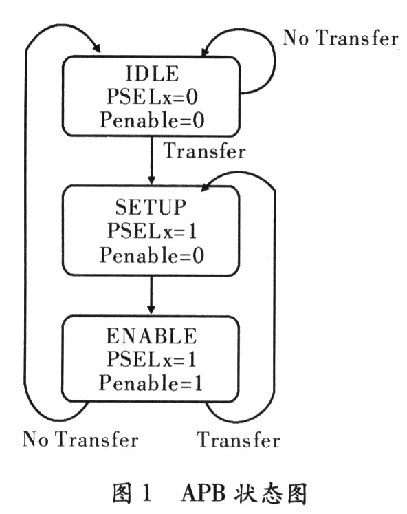
The three states of APB are described as follows:
IDLE: The default initial state.
Setup: When there is a transfer request, the bus will enter the Setup state. When PSELx, the signal is selected. The bus only stays in the Setup state for one cycle and will enter the Enable state on the rising edge of the clock.
Enable: In the Enable state, PEnable is valid, the address signal, the read/write signal, and the selection signal will remain stable when the state is from Setup to Enable. The Enable state only maintains one clock. If no transmission occurs, the system will return to IDLE. If a transmission occurs, the system state will enter the Setup state. Short pulse interference is allowed when going from the Enable state to the Setup state.
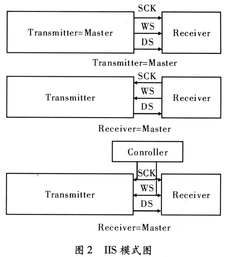
IIS bus: In the IIS standard of Philips, both the hardware interface specification and the format of digital audio data are specified. The IIS bus has three data lines for data transfer: data transfer line (DS), select line (WS), and clock line (SCK). In the data transmission process, the transmitting end (Transmitter) and the receiving end (Receiver) have the same clock signal, and when the transmitting end is used as the master device, a bit clock signal, a command (channel) selection signal and data are generated. In an integrated system, there may be several senders and receivers, making it difficult to identify the sender. In such a system, a controller (Controller) can be set as the master device of the system to identify the data stream of the multi-channel digital audio signal, and at this time, the transmitting end becomes a slave device under the control of the external clock (Stave), the system The master device can also be combined with the sender or receiver, which needs to be activated by hardware or software settings. It has 3 modes, as shown in Figure 2.
IIS has a timing signal diagram as described below. Serial clock signal (SCK): that is, corresponding to each bit of digital audio, SCK corresponds to 1 pulse. SCK frequency = 2 × sampling frequency × number of samples.
Channel selection signal (WS): Used to switch the data of the left and right channels. The frequency of WS is equal to the sampling frequency.
Serial data signal (SD): is the audio data represented in two's complement.
Typical timing is shown in Figure 3.
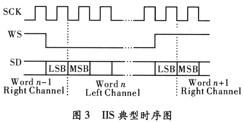
The IIS format signal, regardless of the number of valid data, the highest bit of the data is always transmitted first, in the WS change, that is, the second SCK pulse after the start of a frame, so the highest bit has a fixed position, and the lowest The position of the bit is dependent on the number of significant digits of the data. In other words, the effective number of bits at the receiving end and the transmitting end can be different. If the effective number of bits that can be processed by the receiving end is less than that of the transmitting end, the excess low-order data in the data frame can be discarded. If the receiving end can process more effective bits than the transmitting end, it can make up the remaining bits by itself (often complementing zero) . This synchronization mechanism makes the interconnection of digital audio devices more convenient and does not cause data misalignment. In order to ensure the correct transmission of digital audio signals, the sender and receiver should use the same data format and length. The data length can be different for the IIS format.
2 Audio IP module design Audio IP module, complete the conversion of APB bus protocol to IIS protocol, realize audio output, and set various registers and interrupt output according to task requirements. The audio output module (APB_IIS) is a block diagram, as shown in Figure 4.
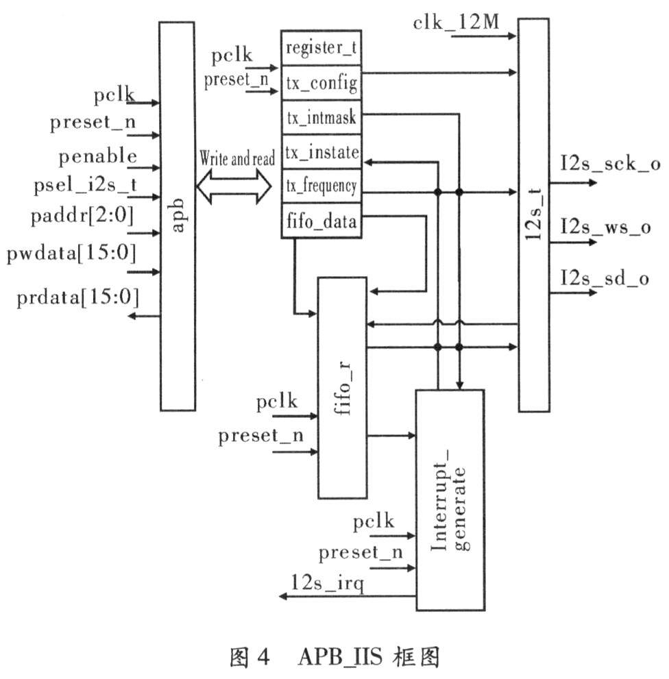
The APB_IIS module consists of the following five modules: the APB interface module. The APB interface module mainly complies with the AMBA protocol and completes the decoding of read and write data. It conforms to the APB protocol completion register read and write, realizes the configuration of the register register_t, and reads and writes the status.
The register module (register_t) completes the setting of various function registers. The register_t module contains the configuration register module (tx_config), the mask register (tx_intmask), the status register (tx_instate), the frequency configuration register module (tx_frequency), and the FIFO write data address (fifo_data).
The function of the FIFO module (fifo_t) is to buffer data from a high-speed clock domain to the low-speed clock domain and generate a flag signal for interrupt generation.
The IIS interface module (i2s_t), the i2s_t module follows the IIS protocol and completes the output of the data.
This module meets the following functional requirements:
(1) transmitting audio (Transmitter) module;
(2) Main mode, provided by the clock from the outside (12 M);
(3) Support timing two modes of audio output;
(4) The frequency divider is implemented 8/11/12/16/22.059/24. /32/44.11/48 (kHz) frequency data transmission;
(5) The internal counter completes the counting of 16 audio data;
(6) Parallel conversion of data.
The interrupt module (interrupt_generate), the interrupt signal is generated by the FIFO module's flag signal and the mask register (tx_intmask) signal to generate an interrupt signal to the system's interrupt controller.
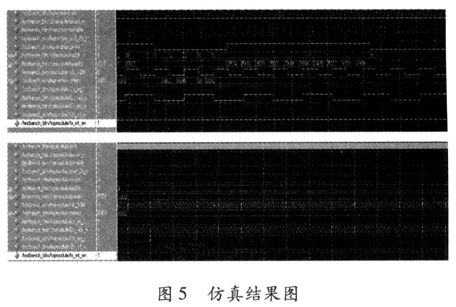
3 Simulation Results Figure 5 shows the local waveform simulation of the APB interface logic read and write timing and IIS output timing. Timing simulations demonstrate compliance with specifications and functional requirements.
4 Conclusion In the article, according to the agreement and actual needs, design an APB to IIS module, specifically describes the protocol, functional specifications, complete RTL code description and functional verification, and get the correct portable audio IP module. Since the module is composed of discrete modules, it is very easy to modify the module according to actual needs.
Schottky Diode,Schottky Barrier Diode,Schottky Diode Forward Voltage,Sic Schottky Diode
Shenzhen Kaixuanye Technology Co., Ltd. , https://www.icoilne.com