1 Introduction
This article designs a headphone amplifier circuit with a common cathode amplifier as the input stage and an SRPP amplifier circuit as the output stage. A micro-variable equivalent model is established for this circuit, a reasonable device is selected, and the corresponding parameters are controlled through theoretical calculations, so that the amplifier can better drive the headset to work.
2 Input level
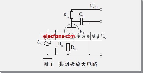
The input stage uses a common-cathode amplifier circuit composed of an electron tube triode, and its circuit schematic is shown in Figure 1. The resistors RL1, Rk1 and Rg1 in the figure are connected to the anode, cathode and grid of the electron tube respectively, so that the electron tube establishes a stable working point, and at the same time has appropriate gain and appropriate local negative feedback. V1 can choose commonly used electronic transistors, such as single transistor ECC92, or one transistor in double transistor ECC82, 12AU7, 5814 and other models. The working principle is different from the bipolar transistor in the transistor, but it is similar to the field effect transistor. Voltage-type amplifier device, its main parameters are transconductance gm, internal resistance rp and amplification factor μ, and the three meet:


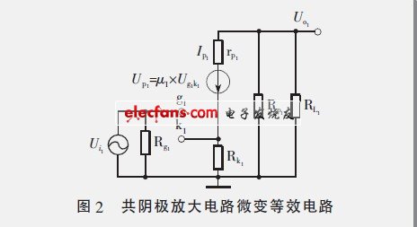
The micro-variable equivalent circuit of this circuit is shown in Figure 2, where the electron tube is regarded as a controlled voltage source. In the figure, the input voltage can be expressed as:


In formula (2), Ug1k1 is the voltage across the grid and cathode of the tube, and Uk1 is the voltage across the cathode resistance Rk1:

The output voltage of the common cathode amplifier circuit is:

The voltage magnification is:

Usb Hdmi Hub,Usb a Adapter,Usb Aux Adapter,Usb Port Extender
Pogo Technology International Ltd , https://www.pogomedical.com