Abstract: The matching calibration protocol based on CAN bus is used to match and calibrate the electronic control unit in the local area network of the vehicle controller. The working mechanism of CCP protocol for calibration is analyzed. The implementation method based on CCP calibration using CANape is discussed. The software interface and specific calibration process of CANape and controller underlying program are described. The practical application results show that this method can quickly and effectively achieve the matching calibration of each controller in the automotive network.
This article refers to the address: http://
At present, the distributed system based on CAN (Controller Area Network) bus is widely used in the field of automotive electronics. The calibration of electronic control unit has become an important part of the development of automotive electronic control devices. CCP (CAN Calibration Protocol) is a CAN bus-based ECU (Electronic Control Unit) calibration protocol [1], which has been applied in many European and American auto manufacturers. The CCP protocol can quickly and effectively calibrate automotive electronic control units. .
However, based on the calibration of the CCP protocol, a driver (CCP driver) supporting the CCP protocol needs to be implemented inside the ECU. Most applications currently use the free CCP driver provided by Vector [2]. Considering that the ECU underlying program and the CAN driver implementation are different, the integration of the CCP driver into the ECU [3] is not a one-step process, which requires the CCP protocol itself, the calibration tool and the calibration tool and the ECU. The communication has a detailed and in-depth understanding. During the development of the calibration system, a large amount of time was spent on combining the previous CCP driver with the ECU. Based on a brief introduction to the CCP protocol, this paper provides an example of a common ECU and CCP driver to help shorten the entire calibration development cycle.
CANape [4] is an ECU calibration and testing tool. In combination with the CCP protocol, not only can the ECU be calibrated, but also the memory can be accessed and operated while the ECU is running. This makes CANape not only a powerful calibration tool, but also a powerful assistant for the development of electronic control units. However, in terms of use, CANape's pre-configuration is cumbersome, and there are currently few relevant materials in China. This article will introduce CANape and look at how to use CANape to complete ECU calibration based on the CCP protocol.
1 CCP agreement and working principle
The CCP protocol is an integral part of the ASAP (Arbeitskreis zur Standardisierung von Applikationssystemen) logo. As an application system standardization working group, ASAP aims to provide common software and hardware interface standards to solve the interface mismatch problem caused by controllers provided by different manufacturers.
1.1 CCP communication method
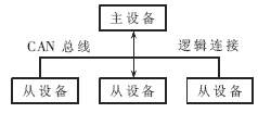
The ECU calibration based on the CCP protocol uses a master-slave communication method, as shown in Figure 1. The master device is connected to multiple slave devices through the CAN bus. The master device is the Measurement Calibration System (MCS), the slave device is the ECU that needs to be calibrated, and the car controller is the vehicle controller.

Figure 1 CCP communication method
According to the CCP protocol, the master device first establishes a logical link with one of the slave devices, and then sends a command to the slave device through the master device to initiate data communication between the two. When the master device wants to access another slave device, it first disconnects the logical connection with the current slave device and establishes a new logical connection with the next slave device before starting communication.
1.2 Working Mode of CCP Agreement
The CCP defines two modes of operation: the Polling mode and the DAQ (Data Acquisition Command) mode. In the query mode, each communication between the master device and the slave device is initiated by the master device sending a command. After receiving the command from the master device, the slave device performs the corresponding operation and feeds back a frame of the message. This kind of work mode requires the "one question and one answer" information interaction between the host and the slave machine, the work efficiency is not high, but the implementation is simple, and the ECU memory resources are small. The DAQ mode enables the slave device to automatically transfer data to the master device in a certain period according to the command control of the master device. In DAQ mode, the master device first sends a command to request DAQ. After receiving the slave device, it configures and organizes the data to be uploaded according to the parameters in the command, and then automatically uploads data to the master device according to a certain period. This mode does not require the host to gradually control through commands, and the work efficiency is high, but the implementation is more complicated. If the amount of data to be uploaded is large, it will occupy a large amount of ECU memory space.
1.3 CCP message frame structure
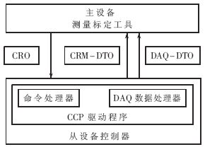
The calibration based on the CCP protocol only occupies two frames of CAN messages, which are the command receiving object CRO (Command Receive Object) and the data transmission object DTO (Data Transmission Object), as shown in FIG. 2 . The CRO is sent by the master device to the slave device, and the DTO is the message fed back from the slave device. Both are identified by their own ID identifier (CRO_ID and DTO_ID).

Figure 2 CCP protocol master and slave communication
The ID identifiers of CRO and DTO are defined by the communication protocol. The CCP protocol only defines the data fields of CRO and DTO in detail. According to the CCP protocol, the first byte of the CRO data field is the command code CMD (Command Code), and the CCP protocol specifies a total of 28 commands [1]. The slave device uses the CMD code to determine which command the master device requested. The second byte of the data field is the command counter CTR (Command Counter). The remaining 6 bytes are command parameters, and each command has its own corresponding command parameter.
The message fed back from the device is called DTO. According to the CCP agreement, DTO is subdivided into three categories:
Command Return Message (CRM): A feedback message sent by the slave device for the CRO.
Event message: When the slave device detects an internal error mechanism, the slave device sends it to the master device to report its current running status, and requests the master device to suspend the current working process to handle the error.
DAQ-DTO (Data Acquisition-DTO): Used in the DAQ mode, organized by the slave device and periodically sent to the master device.
The first byte PID (Packet ID) of the DTO message defines the type of DTO, 255 represents CRM, and 254 represents an event message. The second byte is the command return/error code ERR (Command Return-/Error Code). For CRM, the master learns the execution of the command from this byte; for event messages, the master knows from this bit which error occurred inside the slave. The third byte CTR is a command counter, and the bit value corresponds to the CTR value of the corresponding CRO. The remaining 5 bytes are the data field, which stores the data or information requested by the master device.
2 Interface program implementation based on CCP protocol
Calibration based on the CCP protocol requires both the MCS and ECU applications to support the CCP protocol. This part of the application is called the CCP driver. This article uses the free CCP driver provided by Vector [2]. Since the CCP protocol is based on the CAN bus, the combination of the CCP driver and the ECU is mainly divided into two aspects: the CAN driver and other applications.
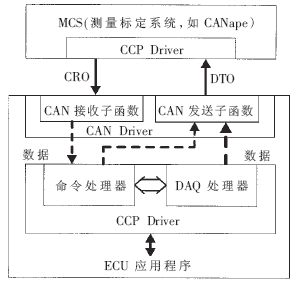
The combination of CCP driver and CAN driver is shown in Figure 3. It is mainly divided into the following two aspects:

Figure 3 CCP calibration program interface
· Transmitter: DTO is uploaded to the MCS in the format of CAN message through the CAN subroutine function.
· Receiver: The command sent by the master device first enters the receive subfunction of the CAN driver in the format of the CAN message. After it is judged to be the CRO, it is further handed to the command processor for processing.
As a main component of the CCP driver, the command processor is responsible for interpreting the received CRO through its CRM code, performing corresponding operations, organizing feedback data and calling CAN to send sub-functions. The DAQ processor supports the DAQ working mode. When the command processor determines that the received command is a DAQ request, it further transmits the data to the DAQ processor, and the DAQ processor organizes the data and directly calls the CAN sending sub-function to the DAQ-DTO. The form is periodically uploaded to the master device.
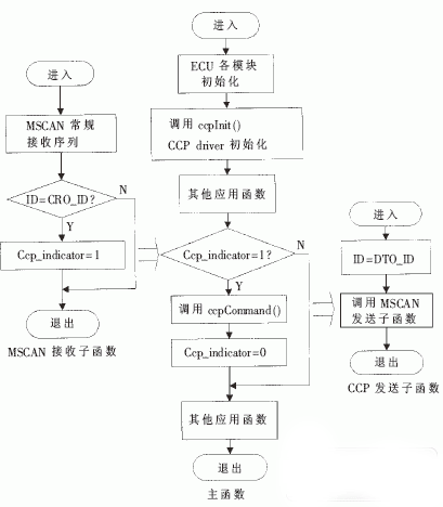
The basic CAN communication flow based on the CCP protocol is shown in Figure 4. After receiving the message, the ECU transfers to the CAN receiving sub-function. After the normal receiving process, it judges the ID identifier of the message. If it is CRO_ID, the CCP flag bit (Ccp_indicator) is set. Since the message is received in the interrupt mode, in order to avoid the excessive interruption time and affect other programs or programs with lower interrupt level, after the ID identifier is judged, the command processor of the CCP driver is not directly called in the function. . The call to the command processor takes place in the main function.

Figure 4 Basic flow chart of the interface program
The main function calls the ccpCommand() subfunction of the CCP driver by judging the status of the flag bit. This function is the main component of the command processor, and is also the interface function between the command processor and the CAN driver. It is responsible for interpreting and executing the received CRO commands, calling other functions in the CCP driver, processing data and organizing data that needs feedback. .
ccpCommand() sends a frame of DTO by calling the CCP send subfunction ccpSend() in the CAN driver. ccpSend() must be implemented in the CAN driver and called by the CCP driver. According to the actual situation, the CAN transmit subfunction is directly implemented in the form of ccpSend(), or a ccpSend() subfunction is added on the basis of retaining the original transmit subfunction, in which the CAN send subfunction is called to complete the DTO transmission. .
The CCP protocol ensures normal communication between the master device and the ECU. After each transmission, the program must check whether the DTO has been sent by calling the ccpSendCallback() subfunction in the CCP driver. Otherwise, the next frame message cannot be sent. The location of the function call is different for different CAN driver implementations. Finally, the main function clears the CCP flag and waits for the next CRO command.
A complete CCP driver interface also includes interfaces to other ECU applications. After each initialization of the MCU, the main function calls the CCP initialization sub-function ccpInit() of the CCP driver to clear the data that was left in the ECU memory for the next calibration, and prepare for the next calibration and measurement.
The CCP protocol defines a total of 28 commands. Each command corresponds to a corresponding set of sub-functions in the CCP driver, representing different functions, such as EEPROM calibration and DAQ working mode. The user can choose to implement some or all of the functions according to actual needs. For each new feature added, a program interface [3] that opens the function must be added to the underlying program. For EEPROM calibration, the ECU application should include the EEPROM module subfunction and the call interface between the command processor and the EEPROM module.
3 CCD-based calibration using CANape
CANape [4] is an ASAP-based ECU test and calibration tool from Vector, Germany. It is connected to the ECU through a controller hardware interface. The common physical connection between the two is the CAN bus based on the CCP protocol. CANape can communicate with the controller only if there is a program interface supporting the CCP protocol in the underlying program of the controller.
CANape offers a variety of functions: online data evaluation, offline evaluation, data management, FLASH programming, parameter calibration, and ASAP2 data editor. In addition, data uploaded by the CAN bus during the test can also be displayed and saved on the computer via CANape for offline calibration and data evaluation.
3.1 ASAP2 controller description file and ASAP2 editor
The communication between CANape and the controller requires a description file support. This file is called the ASAP2 controller description file [4]. CANape's parameter calibration and data measurement for the controller are based on this file, which records the detailed information of each parameter in the controller, such as the calibration parameters and the storage address, storage structure, data type and conversion of the measured variable in the controller. Formulas, etc. In CANape, each calibration parameter and measurement data will have a variable name such as engine temperature and cooling water temperature. When CANape needs to access a variable, it will find the storage address, data length and other information of the variable in the controller according to the variable name in the ASAP2 description file, and then operate, as shown in Figure 5.

Figure 5 ASAP2 controller description file
To facilitate user maintenance and modification of ASAP2 files, CANape integrates an ASAP2 database editor to generate and modify ASAP2 controller description files. All information can be set and modified in the form of a dialog box. The database editor can also work in standalone mode to generate a controller description file in ASAP2 format.
When the ECU's underlying program is modified, the memory address of some calibration parameters and measurement data may change. Although CANape can still be calibrated, the modification is not the parameter that needs to be calibrated, but the current storage address under the original address after the program change. New unknown data. In order to simplify the cumbersome manual modification of the address and prevent the normal operation of the program by arbitrarily modifying a certain data, CANape supports automatic updating of the information in the ASAP2 file through the linker map file. The Map file is a mapping file generated by the compiler when the ECU underlying program is compiled. The ASAP2 file can be automatically updated through the Map file.
3.2 CANape usage configuration
Each ECU that needs to be calibrated is configured in CANape.
CANape has defined a total of 28 commands to implement different functions. There are check boxes in the configuration page. The configuration of the controller must match the specific implementation of the CCP Driver in the ECU's underlying program. Only if the program interface of a function is already open, can this function be selected in CANape [2][5].
3.3 Parameter calibration in CANape
In CANape, the variable to be calibrated is called the calibration parameter, and CANape defines the calibration as modifying the content of the variable stationed in the ECU's memory. CANape supports a variety of calibration methods. The calibration method here refers to how to initialize, rewrite, and save the memory area where the calibration parameters are located. CANape specifies different calibration methods depending on the address space (ROM, FLASH or EEPROM) in which the calibration parameters are located.
When the calibration parameters need to be stored in the FLASH or ROM, after the ECU is powered on, the program first copies the initial value of the calibration parameters into the RAM. In CANape, the RAM used to store the calibration parameters is called the Calibration RAM. During the calibration process, CANape modifies the parameter values ​​in the Calibration RAM. After the calibration is completed, the contents of the RAM are copied back to the FLASH or ROM.
When the calibration parameters are stored in the EEPROM, there are two calibration methods. The first method is the same as the above method. First, the calibration parameters are copied to the RAM, and the data in the RAM is overwritten to the EEPROM after the calibration is completed. In addition, the parameters in the EEPROM can be directly rewritten. This method requires frequent erasing of the EEPROM, but does not occupy extra RAM space.
Since the automotive electronic network system has begun to be widely used, the matching calibration of the electronic control unit based on the network connection has been greatly different from the traditional matching calibration method, especially the CAN-based matching calibration technology has become a research. And the focus of the application.
The CCP-based matching calibration using CANape realizes the unification of the calibration tool and content. According to this method, the matching calibration of the electronic control unit of the automobile can be performed quickly and effectively, and good results are obtained in practical development and application.
Introducing VOSOON, the premium electronic cigarette brand that offers high-quality products with a wide variety of types. Featuring the latest dual-mesh technology, VOSOON delivers a rich and satisfying vaping experience with its unique and beloved design. With abundant vapor production, VOSOON offers both disposable and replaceable pod systems at a reasonable price. Choose VOSOON for a premium vaping experience.
VOSOON Vape,VOSOON Disposable Vape,VOSOON Prefilled Pod Kit,Prefilled Disposable Vape,VOSOON E-cig
TSVAPE Wholesale/OEM/ODM , https://www.tsvaping.com