Common components of motor control loop
Button â–¼
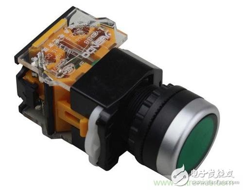
The buttons are divided into a start button, a stop button, and a mechanical interlock button. The first two have a total of 4 posts, the latter has 6 posts.
The start button is mostly green, and the internal is normally disconnected. After the button is pressed, the inside is closed, and then released and then disconnected;
The stop button is mostly red, and the interior is normally closed. After the button is pressed, the interior is disconnected, and then released and closed.
The mechanical interlock button can be regarded as a double-throw switch with a total of 6 binding posts. Usually the left terminal is connected. After pressing, the right terminal is connected. After the release, the left terminal is connected. As a start button or stop button.
The button is generally indicated by SB. If there are multiple buttons at the same time, the number will be added after the SB, such as SB1, SB2.
Contactor / Relay â–¼
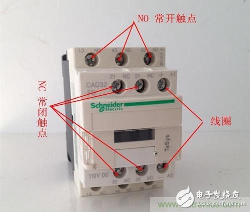
The picture above is a contactor, the relay is small compared to it, but the principle is the same. There are a total of 12 binding posts in two rows (2 binding posts, one in and one out). In the top row of terminals, there are 2 sets of normally closed contacts, and 1 set of coil contacts, and the lower row has 3 sets of normally open contacts.
Working characteristics: When the coil is not energized, the normally closed contact is closed and the normally open contact is opened; after the coil is energized, the normally closed contact is opened and the normally open contact is closed.
Contactors, regardless of which contact or coil, are indicated by KM. If there are multiple contactors, add numbers after KM, such as KM1, KM2. All contacts and coils of the same contactor are marked with a set of labels, such as the normally open contact of the contactor KM1, the normally closed contact and the coil. The marks in the circuit diagram are all KM1.
Jog and linkage
Jog: The motor starts when the button is pressed, and the motor stops when released.
Linkage: When the button is pressed, the motor starts, and after the release, the motor continues to run.
Circuit â–¼
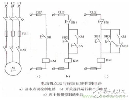
In the above figure, the left side is the main loop, and the right side a, b, and c are three different control loops.
In Figure a, the button SB is pressed and the motor is started. After the release, the motor stops. It is a typical jog control.
In Figure b, when the circuit breaker SA is disconnected, the button SB2 is pressed, the contactor coil KM is energized, the normally open contact KM is closed, but there is a circuit breaker under the normally open contact KM to disconnect it, so although the motor is now Start, but it will stop after being released. After the circuit breaker SA is closed, the button SB2 is pressed, and the contactor coil KM is energized. At this time, the normally open contact KM is closed, so that after the SB2 is released, the motor can still operate normally. At this point the motor is interlocked. Therefore, this diagram can manually control the jog or interlock state.
In Figure c, there is no circuit breaker, instead a mechanical interlock switch SB3. When the button SB2 is pressed, the contactor coil is energized, the normally open contact KM is closed, the motor is started, and after the release, since the normally open contact is still closed, the motor operates normally. When button SB3 is pressed, the button normally closed contact SB3 under the normally open contact of the contactor is opened, and the normally open contact of the button SB3 is closed, the motor is started, and the motor is stopped after being released (the contactor normally open contact is not at this time) Access circuit). Therefore, this circuit can directly press SB3 when the motor is linked, and it becomes jog.
When the motor is interlocked, after the start button is released, the normally open contact KM is closed due to the energization of the contactor coil, and the motor can be continuously operated. This concept is called “self-lockingâ€.
Motor jog and linkage is just a concept, no one wants his own motor to jog. Here we only need to know how to keep the motor running continuously.
Remote control of the motor
This article takes two places to control the motor as an example. Multiple control of the motor is generally divided into remote control and local control. That is, the start button is placed in a different button box, and then the button box is installed at a place to be controlled.
Circuit â–¼
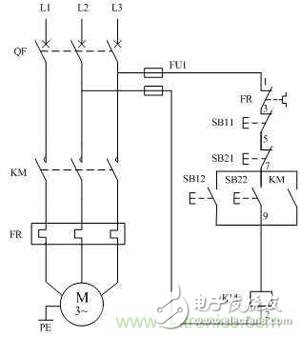
With the knowledge of jog and linkage, the role of the contactor KM in this figure need not be said. In the figure, SB11 and SB21 are stop buttons, and SB12 and SB22 are start buttons. One of the start button and the stop button is installed in the same button box, and the other two are also installed in another button box. Two button boxes can be placed next to the control room and the motor.
Physical connection diagram â–¼
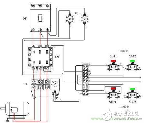
When controlling the motor in different places, you only need to pay attention to the fact that the stop buttons are all connected in series, and the start buttons are all connected in parallel.
Motor sequence starts
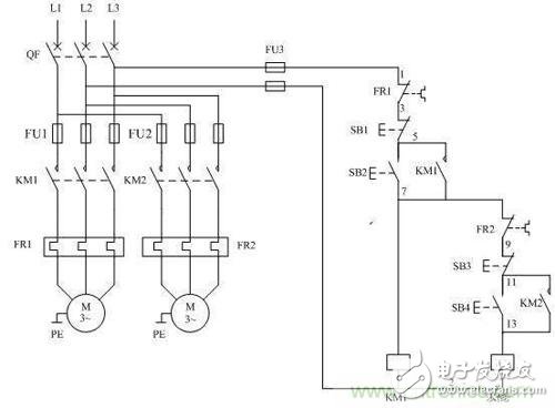
The two motors M1, M2 are sequentially activated as an example. M2 is required to start after M1 is started, and M1 can be started separately.
Circuit â–¼
2.0mm (0.079") Pitch Pin Headers
2.0mm pin headers are board-to-board or PCB to PCB Connectors rated for 250VAC and an industry-leading current of 3.0A. Antenk offers numerous configurations for this pin header. Designed for low-profile applications, this pin header is made from high-temperature thermoplastic and is offered with several means of connections and mounting styles such as through-hole (THM) or surface mount (SMT) and can be in vertical (straight), elevated or at a right angle configuration/orientation
Pin header customization is also available upon your request. The 2.0mm pitch pin header is highly recommendable for signal and low power PC board connections when space is at a premium and when 1.0mm and 1.27mm pitch headers cannot dissipate the required current. In addition, the 2.0mm pitch pin header holds an excellent mating quality that fits with various types of female connectors.
Automotive, Heavy Duty Military and Marine
2.0mm pitch pin headers are for not only suitable for densely packed equipment requiring weight reduction and downsizing but also for automotive connections, built to be robust in tough and harsh conditions.
Battery Connections
Rechargeable battery packs, battery balancers, battery eliminator circuits. Battery connections rely on the ability of the current to pass reliable and solid current. This prevents overheating in the circuit and voltage drop.
Medical Diagnostic and Monitoring equipment
Communications: Telecoms and Datacoms
Industrial and Automotive Control and Test
2.0mm pitch pin (male) headers are offered in either Surface-mount or Through-hole mount termination. At one side of this pin header is a series of pins which can either be mounted and soldered directly onto the surface of the PCB (SMT) or placed into drilled holes on the PCB (THM).
Best used for high-reliability products that require stronger connections between layers.
Aerospace and military products are most likely to require this type of mounting as these products experience extreme accelerations, collisions, or high temperatures.
Useful in test and prototyping applications that sometimes require manual adjustments and replacements.
2.0mm vertical single row header, 2.0mm vertical dual row header, 2.0mm Elevated single row pin header, 2.0mm Elevated dual row pin Header, 2.0mm Right-angle single row header and 2.0mm Right-angle dual row header are some examples of Antenk products with through-hole mount type.
Surface-Mount
The most common electronic hardware requirements are SMT.
Essential in PCB design and manufacturing, having improved the quality and performance of PCBs overall.
Cost of processing and handling is reduced.
SMT components can be mounted on both side of the board.
Ability to fit a high number of small components on a PCB has allowed for much denser, higher performing, and smaller PCBs.
2.0mm Right-angle Dual Row pin header, 2.0mm SMT Single row pin header, 2.0mm SMT Dual row pin header and 2.0mm Elevated Dual Row Pin Header are Antenk`s SMT pin headers.
Soldering SMT pin connectors can be done at a maximum peak temperature of 260°C for maximum 60 seconds.
2.0mm pitch headers may be further classified into pin orientation as well, such as vertical or straight male header or right-angle male header.
Vertical or Straight Pin (Male) Header Orientation
One side of the series of pins is connected to PCB board in which the pins can be at a right-angle to the PCB surface (usually called "straight" or [vertical") or.
Right-Angle Pin (Male) Header Orientation
Parallel to the board's surface (referred to as "right-angle" pins).Each of these pin-types have different applications that fit with their specific configuration.
PCB Connector Stacking
Elevated Pin Header Orientation
Elevated pins aka Stacked Pins or Mezzanine are simply stacked pin headers providing an exact distance requirement between PCBs that optimizes electrical reliability and performance between PCB boards.
Profile Above PCB
This type of configuration is the most common way of connecting board-to-board by a connector. First, the stacking height is calculated from one board to another and measured from the printed circuit board face to its highest insulator point above the PCB.
Single, Dual, Triple and Four Row Number of Rows
For a 2.0mm straight or vertical male pin header, the standard number of rows that Antenk offers ranges from 1 to 4 rows. However, customization can be available if n number of rows is needed by the customer. Also, the number of contacts for the single row is about 2-40 pins. For dual row, the number contacts may vary from 2-80 pins. For triple row, it`s 2-120 pins, while for four-row, it`s 2-160 pins.
Pin Material
The pins of the connector have been designed with copper alloy. With customer`s demand the pins can be made gold plated.
Breakaway design
The pin headers are also equipped with a breakaway design making them fully compatible with their female receptacles.
Custom 2.0mm Pitch Pin Headers
Customizable 2.0 mm pitch pin headers are also available, making your manufacturing process way faster as the pins are already inserted in the headers, insulator height is made at the right size and the accurate pin length you require is followed.
Parts are made using semi-automated manufacturing processes that ensure both precision and delicacy in handling the headers before packaging on tape and reel.
Tape and Reel Packaging for SMT Components
Antenk's SMT headers are offered with customizable mating pin lengths, in which each series has multiple number of of circuits, summing up to a thousand individual part number combinations per connector series.
The tape and reel carrier strip ensures that the headers are packaged within accurately sized cavities for its height, width and depth, securing the headers from the environment and maintaining consistent position during transportation.
Antenk also offer a range of custom Tape and reel carrier strip packaging cavities.
Pcb Pin Header,2.0Mm Male Header,2.0Mm Male Header Pins,2.0Mm Pin Header,0.079in Male Header, 0.079in Pin Header Connector
ShenZhen Antenk Electronics Co,Ltd , https://www.pcbsocket.com