With the increasing popularity of big data, the transmission bandwidth requirements of the core network have been greatly improved every year, so the transmission technology needs to be further developed to meet such market demand. At present, the idea of ​​further improving the bandwidth mainly includes several aspects: one is to further increase the signal rate; the second is to increase the number of transmission links; the third is to increase the amount of information in the same time window (to increase the number of data packets carried in the same Symbol) The PAM4 (Pulse Amplitude ModulaTIon) modulation pattern format is a method for increasing the amount of information in the same time window. This article provides a brief introduction to the basic concepts of PAM4 and how to test PAM4 signals.
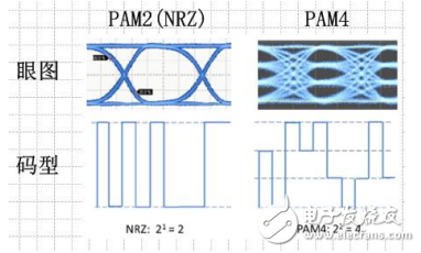
First, NRZ and PAM4 patternFigure 1 below shows the eye pattern bit pattern of the NRZ pattern and the PAM4 pattern. The NRZ code contains two levels and the PAM4 code contains four levels. The PAM4 code can be seen as a superposition of two NRZ codes, one symbol of a NRZ code contains one bit, and one symbol of a PAM4 contains two Bits.

Figure 1 NRZ pattern and PAM4 pattern
Second, the application of PAM4 pattern in high-speed Ethernet and coherent optical communication1, high speed Ethernet
Ethernet 802.3bj is a 100Gb/s backplane and cable standard, and the signal pattern used can be NRZ code or PAM4 code. Because the transmission medium is copper, the bandwidth is limited. Therefore, if the NRZ code is used, the rate is difficult to be very high. If the PAM4 pattern is used, two bits can be transmitted in each Symbol, so the same wave can be used. In the case of special rate, the data information is doubled. But the PAM4 level is more sensitive to noise.
2. Baseband modulation in coherent optical communication
The more mature 100GbE coherent optical signal application is shown in Figure 2 below. The optical signal transmission of 100GbE is realized by bipolar QPSK modulation and electrical-to-optical conversion of four 25 Gbps NRZ signals. Two of the 25 Gbps signals in each of the polarities (X polarity and Y polarity) are transmitted by mutually orthogonal I (real part) and Q (imaginary part) using QPSK modulation.

Figure 2 Basic block diagram of 100G DPQPSK coherent optical communication
Four-phase phase shift keying modulation uses four different phase differences of the carrier to characterize the input digital information, which is a quaternary phase shift keying. QPSK is a phase modulation technique at M=4, which specifies four carrier phases, 45°, 135°, 225°, and 275°, respectively. The data input to the modulator is a sequence of binary digits, in order to be able to be quaternary. The carrier phase is combined, and the binary data needs to be converted into quaternary data. That is to say, every two bits in the binary number sequence need to be grouped into one group, and there are four combinations, namely 00, 01, 10, 11 each. One group is called a two-bit symbol. Each two-bit symbol is composed of two bits of binary information bits, which respectively represent one of the four symbols in quaternary. Each modulation in QPSK can transmit 2 information bits, which are transmitted through the four phases of the carrier.
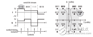
Phase shift keying encodes the signal by changing the phase of the optical carrier. The QPSK signal has 4 phase selections, so 2 bits can be modulated in each cycle or symbol, and the signal can be 00, 11, 01 or 10. Figure 3 below shows how the phase information of the transmitted signal is mapped to the encoded data and constellation. The transmitted data signal consists of a modulated I signal and a Q signal.

Figure 3 QPSK modulated signal transmission and constellation
Since the PAM4 pattern signal contains twice the amount of information of the NRZ pattern signal, if PAM4 is used instead of NRZ, the amount of information transmitted at the same signal rate can be doubled, and the original 100GbE signal throughput can be improved. To 200GbE, as shown in Figure 5. Since the PAM4 signal has 4 levels, it is the baseband modulation level of 16QAM modulation. As shown in Figure 4 below, I and Q respectively transmit 4-level PAM4 signals, each level containing 2 bits of digital information, so that I and Q are added together and each level corresponds to 4 Bitwise digital information. There are a total of 16 types of information combinations transmitted. The diagram on the right of Figure 4 is a constellation diagram of the 16QAM signal.

Figure 4 Transmission and constellation diagram of 16QAM modulated signal

Figure 5 Coherent optical communication transmission system based on PAM4
Third, PAM4 test solutionTeledyne LeCroy has developed a test package specifically for PAM4, which is combined with LeCroy's high-bandwidth oscilloscope for comprehensive analysis of PAM4 signals. Contains the following features:
Clock recovery
Eye
Eye height/eye width measurement
Jitter parameter measurement and decomposition
Noise parameter measurement and decomposition
IsoBER eye contour and bit error rate contour prediction
Eye shift
Level measurement
Tracking/histogram/spectrum
balanced
Simulation of PAM4 signal

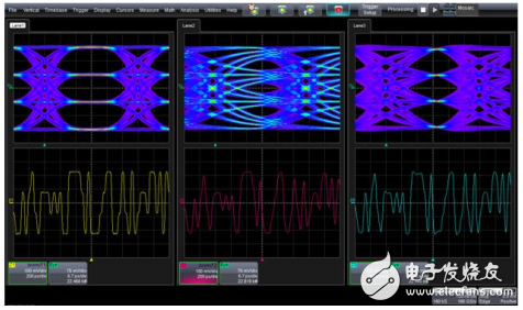
Figure 6 Multi-link PAM4 signal eye diagram test

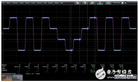
Figure 7 PAM4 signal level test
Over time, battery cables have to be replaced due to corrosion or damage. A bad battery cable can cause intermittent starting issues or lack of power to the vehicle, including arcing or power drains.A battery cable consists of multiple stands of wire encased in synthetic material with different types of battery terminals on each end for a reliable connection. Corrosion is the number one cause of battery cable failure, stopping the flow of electricity.
Battery cable, power cable, battery cable assembly, battery wiring
ETOP WIREHARNESS LIMITED , https://www.wireharnessetop.com