Abstract: Aiming at the common signal amplitude turbulence of voice interface, a voice interface based on voice codec chip AIC23 and digital signal processor TMS320VC5416 is designed. The voice signal automatic gain control (ACC) method based on AIC23 internal variable gain amplifier is studied. The designed voice interface circuit is simple, the sound quality is clear, and the volume is stable.
Key words: variable gain amplifier; multi-channel buffer serial port; automatic gain control; digital signal processor
This article refers to the address: http://
The voice interface includes two functions of acquisition and playback, which is the most basic and critical part of the voice processing system. During voice acquisition, the amplitude of the input signal will affect the subsequent processing; when the voice is played, the amplitude of the output signal will be unstable and the listening effect will be deteriorated. Therefore, voice AGC (Automatic Gain Control) is an indispensable functional unit in the voice interface. TLV320AIC23 (referred to as AIC23) is a high-performance speech codec chip integrated by TI with integrated A/D, D/A converter and variable gain amplifier. It is an ideal choice for designing voice interfaces. The characteristics and structure of AIC23 are introduced in this paper. On this basis, the voice interface and AGC implementation method are given.
1 Introduction to AIC23
1.1 Main features (1) Integrated line input variable gain amplifier (VGA) with a gain range of -34.5 to 12 dB and a step of 1.5 dB;
(2) Integrated line output variable gain amplifier (VGA) with a gain range of -73 to 6 dB and a step of 1 dB;
(3) I/O voltage and data interface are compatible with TI's 54 series DSP.
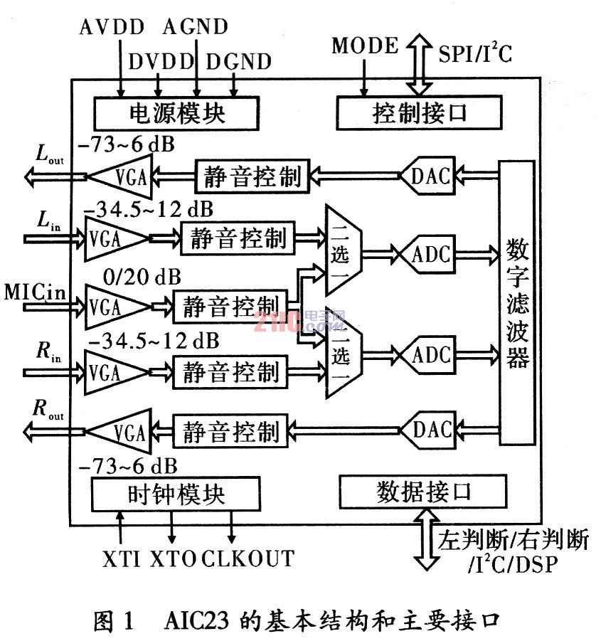
1.2 Basic structure and main interface The basic structure and main interface of AIC23 are shown in Figure 1. The analog voice signal is input from the left and right channel line input pins or the microphone signal input pin, and is respectively obtained by a VGA, a mute control, a multiplexer, an A/D converter, and a digital interpolation filter to obtain a specific sampling rate. The voice signal; the digital voice signal passes through the digital filter, the D/A converter, the mute control and the VGA, and finally outputs the output pin from the left and right channel lines; the working state of the AIC 23 is set by the system microprocessor through the control interface. The control interface mode is SPI/I2C optional (mode pin is set to SPI mode, low is set to I2C mode); AIC23 and microprocessor exchange data through data interface, data interface is left judgment / right judgment / I2C / DSP Mode selectable (set by the microprocessor via the control interface). TI's 54 Series DSPs integrate a multi-channel buffered serial port (McBSP) that seamlessly interfaces with the SPI mode control interface and the DSP mode data interface.

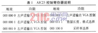
1.3 Control Method AIC23 is a programmable chip with 11 9-bit registers inside, which can be configured by the microprocessor through the control interface to set the working mode and state of the chip. The main register contents are shown in Table 1.

2 voice interface design
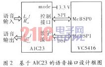
2.1 Hardware Design The voice interface consists of TI's digital signal processor TMS320VC5416 and AIC23, as shown in Figure 2. The VC5416 has three multi-channel buffer serial ports (McBSP), of which McBSP0 is connected to the control interface of AIC23, which is responsible for configuring the internal registers of AIC23. McBSPl is connected to the data interface of AIC23 to complete data exchange with AIC23. The analog voice signal is input from the line input pin and the line output pin is output.

2.2 Interface Configuration (1) Control interface.
Set the control interface to SPI mode by setting the mode pin of AIC23 high. VC54.16's McBSP0 is set to active mode, which generates bit sync signal and frame sync signal, and sends 16-bit single frame to AIC23. The upper 7 bits of each frame are the address of the register in AIC23, and the lower 9 bits are the set value of this register. The configuration of AIC23 in this design mainly includes: line input enable, microphone input mute, data interface set to DSP (main) mode, word length 16 bit, sampling rate 32 kHz.
(2) Data interface.
The DSP mode of the data interface is specifically designed to interface with TI's DSP. The VC5416's McBSP1 operates in slave mode, and the bit sync signal and frame sync signal are generated by AIC23. The data transmission transmitted and received by McBSPI adopts single frame mode, in which the upper 16 bits are left channel data and the lower 16 bits are right channel data.
3 Implementation of the voice AGC method The control method that automatically adjusts the gain of the amplifier with the change of the signal strength is AGC, that is, automatic gain control. The AGC can be implemented by hardware or software. This design makes full use of the VGA integrated in the AIC23 and is implemented by a combination of software and hardware. The implementation method of input and output AGC is shown in Figure 3 and Figure 4.

3.1 Input AGC Implementation Method The input AGC is implemented by a feedback control loop. The detection module performs amplitude estimation on the voice signal received by the McBSP1, estimates the average envelope level of the voice signal, and the gain conversion module compares the average envelope level with the target level, and calculates the gain adjustment amount of the VGA, by the integration module. The gain adjustment amount is accumulated to obtain the target gain value of the VGA, and the target gain value is fed back to the VGA through the McBSP0 and the control interface to realize automatic control of the gain.
(1) Detection module.
The detection module adopts a fast charge and slow release envelope detection algorithm to low-pass filter the input signal to obtain the mean value of the signal envelope. Its expression is
![]()
Where x(n) is the input speech signal, y(n) is the detection result, Mf is the charging time constant, and Ms is the discharge time constant. According to the characteristics of the envelope of the speech signal, the charging time should be on the order of several hundred milliseconds, and the discharge time should be between several seconds and ten seconds. In addition, due to the pause between the phonetic word and the word, the sentence and the sentence, there is only noise during the pause, and the envelope detector should stop working. The method implemented is to set the amplitude threshold Ln. The signal with amplitude lower than Ln is considered as noise, and only the signal with amplitude higher than Ln participates in envelope detection.
(2) Gain conversion module.
The average envelope level y(n) differs from the target level Yaim by ΔG(n)=20 log(Yaim/y(n)), since the input VGA has an adjustment accuracy of 1.5 dB (total 31) File), so the gain adjustment amount ΔG0(n) of the VGA should take the number closest to ΔG(n) and divisible by 1.5. The mapping relationship between y(n) and ΔG0(n), as shown in Fig. 5, y(n) in a certain range corresponds to a unique ΔG0(n), for example, if y(n)∈[ 1.3 Yaim, 1.54 Yaim], then △G0(n)=-3 dB.


3.2 Output AGC Implementation Method The output AGC is implemented by a feedforward control algorithm. The detection module discriminates the speech signal and estimates the average envelope level of the speech signal. The gain conversion module compares the average envelope level with the target level, and calculates the gain adjustment amount of the VGA, and then the initial gain value of the VGA. Add together to get the target gain value of VGA. The target gain value is fed forward to the VGA via McBSP0 and the control interface to achieve automatic gain control.
The implementation method of the detection module in the output AGC is completely consistent with the detection module in the input AGC. The gain conversion method is similar to the gain conversion method in the input AGC, but since the output VGA has an adjustment precision of 1 dB (79 files in total), the output VGA is output. The gain adjustment amount ΔG0(n) should take the nearest integer to ΔG(n).
Conclusion Based on the introduction of the characteristics and structure of AIC23, the design method of voice interface based on AIC23 is given, and the implementation method of voice AGC is explained in detail. Making full use of the AIC23 interface is simple and flexible, the input and output signal-to-noise ratio is high, and the gain is adjustable, so that the designed voice interface circuit is simple, the sound quality is clear, and the volume is stable.
Reflecting Liquid Crystal Display

Reflecting Liquid Crystal Display,Electronic Instrument Displays,Electronic Watch Display,Clock Lcd Display
Dongguan Yijia Optoelectronics Co., Ltd. , https://www.everbestlcdlcm.com