Lithium battery protection board is the charge and discharge protection for the series lithium battery pack; when fully charged, it can ensure that the voltage difference between each unit battery is less than the set value (generally ±20mV), and realize the equalization of each unit of the battery pack. , effectively improving the charging effect in the series charging mode; simultaneously detecting the overvoltage, undervoltage, overcurrent, short circuit, and overtemperature conditions of each single cell in the battery pack, protecting and extending the battery life; undervoltage protection enables each A single battery prevents damage to the battery due to overdischarge during discharge.
The finished lithium battery consists mainly of two major parts, a lithium battery core and a protective plate. The lithium battery core is mainly composed of a positive electrode plate, a separator, a negative electrode plate and an electrolyte; the positive electrode plate, the separator and the negative electrode plate are wound or laminated, packaged, and poured into the electrolyte. After the package is made into a battery core, the role of the lithium battery protection board is not known to many people. The lithium battery protection board, as the name implies, is used to protect the lithium battery. The role of the lithium battery protection board is to protect the battery but not charge it. Stream, there is output short circuit protection.
Lithium battery protection board connectionThere are two ways to design the lithium battery protection board, which are the positive and negative plates. The principle and purpose are the same, but the device does not support the software to modify the settings of the positive and negative protection boards, so it can only be physically correct. Connect to determine the protection mode, and the software used is different. The following describes the connection methods and operation methods of the two protection boards.

The connection method of the battery protection board is generally the same as the negative protection board, the negative pole board, and the positive board. The other methods are not described one by one. The details are as follows:
1. The connection mode of the negative plate is referred to the following table.

2. The negative port is connected to the same port. Please refer to the table below for the wiring sequence.

3. The positive plate is connected to the same port. Please refer to the table below for the wiring sequence.

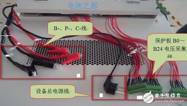
In the process, the battery protection board has many connection methods when testing on non-standard battery equipment, and it is also worthy of familiarity with the test connection. The simple process is as follows:
1. Place the device on a relatively level desktop and adjust the smoothness of the device to make it smooth;
2. Ensure that the humidity of the equipment is in the range of 30~50%. If the humidity is too high, the casing will leak and the electric shock will occur.
3. Connect the appropriate power supply (AC 220V/0.1A), turn on the main equipment power button, and turn on the respective power module buttons.
4. Check if the equipment can display normally and test normally.
Small computer system interface (SCSI) is an independent processor standard for system level interfaces between computers and intelligent devices (hard disks, floppy drives, optical drives, printers, scanners, etc.). SCSI is an intelligent universal interface standard.
SCSI-3
In 1995, the more high-speed SCSI-3, called ultrasci, was born, and the data transmission rate reached 20MB / s. It increases the synchronous transmission clock frequency to 20MB / s and improves the data transmission rate. If 16 bit wide mode is used, the data transmission rate can be increased to 40MB / s. This version of SCSI uses a 68 pin interface, which is mainly used on hard disks. The typical characteristic of SCSI-3 is that the bus frequency is greatly increased and the signal interference is reduced to enhance its stability.
There are many models of SCSI-3. Ultra (FAST-20) has a transmission frequency of 20MHz, a data bandwidth of 8 bits and a transmission rate of 20MBps
Ultra wide has a transmission frequency of 20MHz, a data bandwidth of 16 bits and a transmission rate of 40mbps
The transmission frequency of ultra 2 is 80 MHz, the data bandwidth is 16 bits, and the transmission rate is 80 Mbps
The transmission frequency of ultra 160 is 80 MHz, the data bandwidth is 16 bits, and the transmission rate is 160 Mbps
The transmission frequency of ultra 320 is 80MHz, the data bandwidth is 16 bits, and the transmission rate is 320mbps
The transmission frequency of ultra 640 is 160MHz, the data bandwidth is 16 bits, and the transmission rate is 640mbps
Plastic SCSI Cover
ShenZhen Antenk Electronics Co,Ltd , https://www.pcbsocket.com