Abstract: A common brightness-control circuit for LEDs uses an electrically controlled potenTIometer (EPOT) to achieve digital control of the LED brightness. Replacing the EPOT with an RC network, however, reduces both the IC count and the required number of control lines.
A system in which a microcontroller or programmable logic controls one or more LEDs often requires the capability of controlling LED brightness. A common approach for achieving this adjusts an electrically controlled potenTIometer (EPOT), which in turn, controls the LED driver (Figure 1) . For large systems, however, that approach can require many EPOTs, each requiring two control lines, or address decoding, or both.
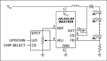
Figure 1. A common brightness-control circuit for LEDs uses an electrically controlled potenTIometer (EPOT) to achieve digital control of the LED brightness.
There is an alternaTIve that reduces the number of ICs and control lines. You can control each LED driver directly with a single output port. Simply replace the EPOT with a simple RC integrator and program the port to output a PWM signal (Figure 2). The average voltage at ADJ (pin 4) varies with the PWM signal and enables the IC (a current regulator for LEDs) to control the LED brightness. An RC time constant at least 50 times the PWM period produces a smooth average voltage across the capacitor . The circuit also includes a 6.65kΩ resistor across the integrating capacitor, which reduces the 5V PWM signal to 1.25V as required by the IC's ADJ input.
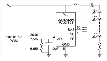
Figure 2. Replacing the EPOT of Figure 1 with an RC network reduces both the IC count and the required number of control lines.
A similar article appeared as a Design Idea in the February 20, 2006 edition of EET.
A system in which a microcontroller or programmable logic controls one or more LEDs often requires the capability of controlling LED brightness. A common approach for achieving this adjusts an electrically controlled potenTIometer (EPOT), which in turn, controls the LED driver (Figure 1) . For large systems, however, that approach can require many EPOTs, each requiring two control lines, or address decoding, or both.

Figure 1. A common brightness-control circuit for LEDs uses an electrically controlled potenTIometer (EPOT) to achieve digital control of the LED brightness.
There is an alternaTIve that reduces the number of ICs and control lines. You can control each LED driver directly with a single output port. Simply replace the EPOT with a simple RC integrator and program the port to output a PWM signal (Figure 2). The average voltage at ADJ (pin 4) varies with the PWM signal and enables the IC (a current regulator for LEDs) to control the LED brightness. An RC time constant at least 50 times the PWM period produces a smooth average voltage across the capacitor . The circuit also includes a 6.65kΩ resistor across the integrating capacitor, which reduces the 5V PWM signal to 1.25V as required by the IC's ADJ input.

Figure 2. Replacing the EPOT of Figure 1 with an RC network reduces both the IC count and the required number of control lines.
A similar article appeared as a Design Idea in the February 20, 2006 edition of EET.
Scooter car also called body car, camera car, balance car etc, and the Scooter Adapter is the important accessory for the scooter car. Yidashun can offer the scooter Adapter from 12V to 48V, such as 12V 8A, 15V 5A, 24V 4A, 36V 2A, 42V 2A and 48V 2A and so on.
Yidashun's electric scooter charger have the advantage of Over-current protection, over-voltage protection, over-temperature protection, under-voltage protection, short-circuit protection, anti-backflow, and automatic shut-off protection etc, to ensure the safety during using.
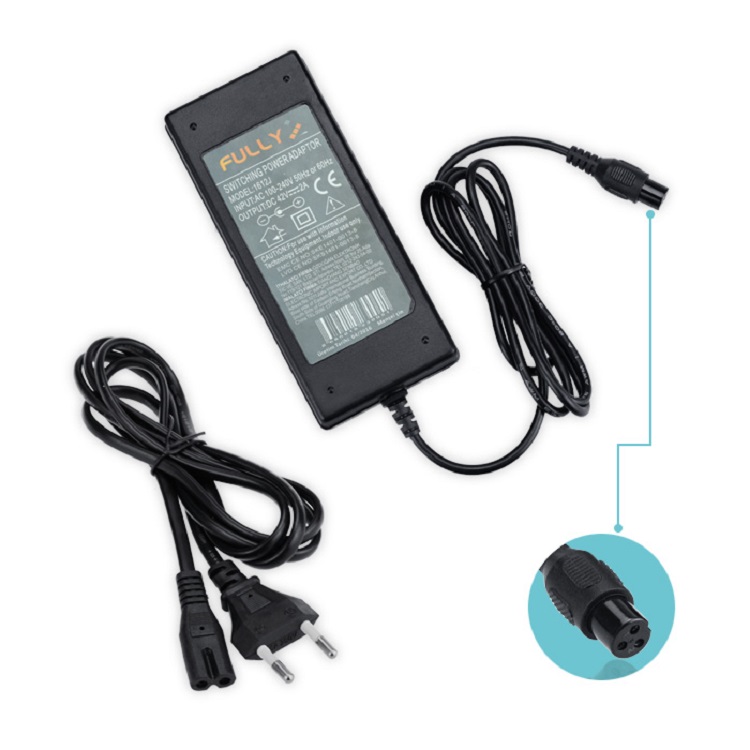
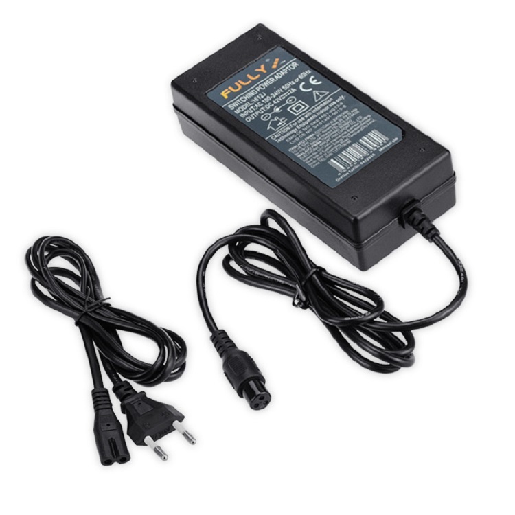

Scooter Adapter
Scooter Adapter,Scooter Battery Charger,Electric Scooter Charger,Razor Scooter Charger
Shenzhen Yidashun Technology Co., Ltd. , https://www.ydsadapter.com