As today's products used in consumer electronics, automotive, and aerospace applications become more complex as they continue to evolve, continuous testing capabilities and ever-shortened test times and time-to-market have made test instruments even more demanding. More requirements.
For instruments such as oscilloscopes, a major requirement is to quickly and reliably detect and trigger events of interest in known signal streams. The more timely the detection of a particular event, the faster the problem generated during the electronic design process can be corrected, saving development and production test time.
This is equally important for oscilloscope vendors. Many vendors offer more than 100 predefined triggers to help users quickly separate common and uncommon signal conditions. This aspect increases flexibility, but on the other hand, choosing the right trigger itself is more difficult than actually capturing the signal because the trigger has a wide variety of types, speeds, bandwidths, delays, and software, and each trigger is There is a trade-off between flexibility and dead time. Understanding each type of trigger and the corresponding trade-offs can help users find the ideal trigger method to increase the chances of a successful trigger event.
Two factors determine the trigger performance of the oscilloscope:
Trigger flexibility describes how easy it is to define trigger thresholds or conditions to accommodate various measured signal condition states to increase efficiency. Most oscilloscopes offer a variety of trigger functions defined by the vendor, including parameter minimum settings such as level or width, but do not provide a way to customize these parameters.

The trigger dead time is the length of time that the oscilloscope cannot detect the trigger between adjacent acquisitions. This means that if the event of interest occurs within the dead time, then it will miss the trigger condition. Triggering dead time is an inherent feature of all trigger architectures, but we can use some methods and techniques to minimize this time. Many oscilloscope vendors offer software-based triggers to increase flexibility, but because of the need for post-processing, such triggers require a long dead time and are therefore not suitable for small-probability and infrequent event detection.
1. Traditional trigger edge triggering (starting to acquire data when a logic signal changes from a high level to a low level or from a low level to a high level) is currently the most common oscilloscope trigger mode. Most of the simple debugging and testing functions are handled by edge triggering, but sometimes more complex triggers are needed to isolate signals of a particular shape or to continuously isolate signals of multiple shapes. The oscilloscope also includes some more advanced trigger options that provide greater flexibility to capture serial protocols such as I2C or SPI as well as advanced event and signal characteristics such as glitches, short pulses, width, slew rate, timeout, and more.

Figure 1. This is a block diagram of an oscilloscope based on digital signal processing. The acquisition memory and signal processing unit determine the acquisition update rate and dead time of the oscilloscope.
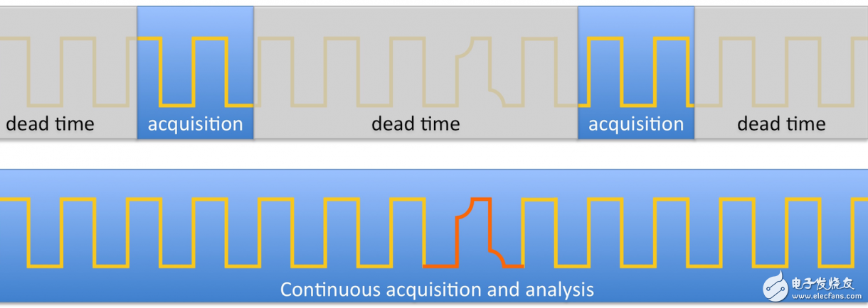
Many trigger conditions are performed in hardware, but more complex trigger options and signal authentication are typically performed in software similar to that in Figure 1. Software triggering provides the best flexibility, but it also increases the necessary data transfer and processing time during which the oscilloscope cannot detect new triggers, as shown in Figure 2. The time period during which the system cannot detect the trigger is called the dead time, which is often longer than the actual data acquisition time—in other words, the oscilloscope trigger system's dead time may occupy more than 95%. This makes it more difficult to detect small or low frequency events and results in longer test times. To make matters worse, the user may mistakenly assume that the expected event did not occur because the probability of the expected event occurring is too low to be detected during the measurement.

Figure 2. This figure shows the data acquisition and analysis process of a traditional oscilloscope where there is a dead time between waveform capture (top) and continuous processing (bottom).
If the oscilloscope's available triggering or signal analysis capabilities do not meet the task's needs, then the user's only option is to take longer waveform segments and download the raw data from those segments to a computer for post-processing to find a specific event. However, this increases the complexity of the overall system design process, and the entire test takes longer due to data transfer delays and the time required for data processing.
2. Generate triggers, no trade-offs While most software-based or smart trigger options can meet the design and testing needs of electronic circuits, these events tend to lengthen product development time if small probability events are not quickly isolated or corrected. Due to the limitations of the oscilloscope's triggering capabilities, users can only use the features provided by the vendor.
If the user can develop his own algorithm within the oscilloscope, then the instrument's functionality can be customized for a specific task, so that it is not limited to the features provided by the vendor. For example, the user can customize the trigger condition for a specific application to specifically capture a certain signal condition, so that no subsequent processing on the PC is required, thereby greatly reducing the test time, as shown in FIG.
The key technology for providing oscilloscopes with the flexibility of online data processing and reprogramming algorithms is FPGAs, which are essentially programmable chips that can execute custom signal processing and control algorithms at high speed through true parallelism. The flexibility of the FPGA allows the user to modify or add specific triggering algorithms, while high-throughput data processing analyzes the data samples in real-time during the acquisition process, rather than processing them later. This avoids dead time, prevents triggering omissions, and helps users detect small probability events faster.
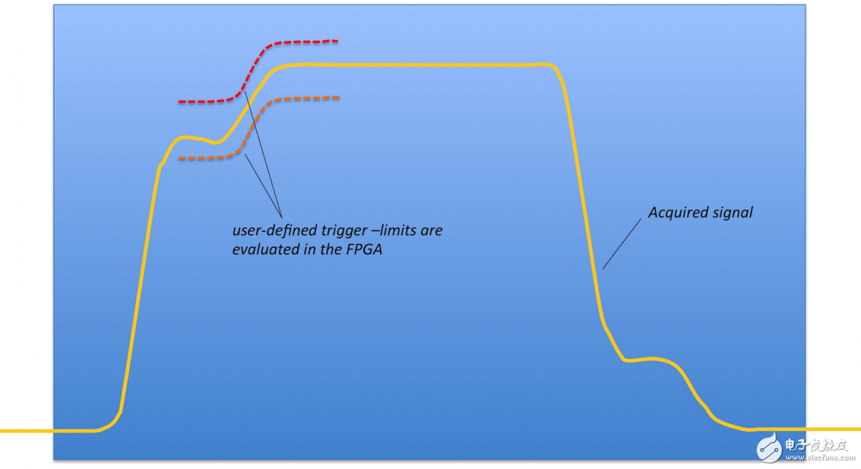
An example of a user-defined trigger is to detect a signal waveform or level transition that does not conform to the standard trigger definition, such as the signal shown in Figure 3. This digital signal shows a non-monotonic edge, which may be due to signal reflection or power failure of the circuit under test. Standard edge or width triggers are unable to detect such undesired signals, and detection using conventional means is essentially impossible. We need to study a new trigger to capture this event accurately and continuously. In order to solve this problem, we need to develop a software trigger; however, this method has a large trigger dead time and cannot detect small probability events quickly. Alternatively, a user-programmable FPGA can be used to provide multiple window triggers. When all window triggers simultaneously detect a valid trigger condition, the acquired samples are compared to the mask to produce a combined trigger to acquire the signal.
Because the FPGA can continuously evaluate the signal in real time, the oscilloscope can capture both a single signal and a continuous signal without dead time between acquisitions.

Figure 3. Capture a specific signal transition using a user-defined trigger; this is implemented in an FPGA of a reconfigurable oscilloscope.
3. Reconfigurable Oscilloscopes Over the years, test engineers have used software tools such as LabVIEW to replace fixed software in traditional benchtop instruments, enabling system testing and automation of measurement results analysis and display, saving test costs. This approach provides flexibility and takes advantage of the latest PC and CPU technologies. However, the needs of users are often not limited to this, they usually need to modify the measurement method of the instrument to better meet the needs of the application.
Traditional off-the-shelf instruments are defined by the vendor and provide only fixed functionality; NI is the first to use FPGA technology to provide a more open and flexible instrument. As a result, hardware is available that combines these two features: fixed, high-quality measurement technology; the latest digital bus integration; user-customizable highly parallel logic that provides low latency and is directly associated with I/O For online processing.

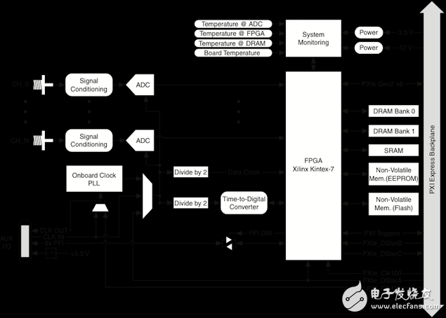
Figure 4. Functional block diagram of the reconfigurable oscilloscope NI PXIe-5171R.
With open software from vendors within the FPGA, users can extend the capabilities of the instrument, such as custom triggers or additional timing or control signals. Users can also implement their own algorithms in FPGAs of software-designed instruments, redefining hardware functions to accomplish completely different tasks. For example, an oscilloscope can be turned into a real-time spectrum analyzer, transient recorder, protocol analyzer, RF receiver, or other instrument.
Equipment cost is a major cost of the test system, and because the number of instruments that need to be purchased and maintained is small, reconfigurable equipment can help users save on equipment costs. This is especially useful for test and instrument functions that require long-term (more than 10 years) use, such as military or aerospace test systems, which often require the reproduction of old instruments that have been eliminated (end of life).
Reconfigurable instruments are ideal for this application because reprogramming can simulate the functionality of older instruments. Test system software works with new instruments with minimal reprogramming and recertification, helping users save money.
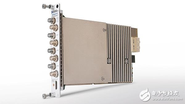
An example of such an instrument is the NI PXIe-5171R reconfigurable oscilloscope, which uses Xilinx Kintex-7 FPGAs to process samples from eight input channels in real time. Figure 4 shows how a user-programmable FPGA can be integrated into the data path and provide access to the instrument's control and timing signals.
4. Conclusion Due to the lack of flexibility and real-time analysis capabilities, traditional oscilloscope triggering methods face challenges in capturing small probabilities and complex events. The new approach leverages FPGA technology to customize triggering to meet complex trigger conditions and real-time signal processing and analysis needs.
ZGAR Aurora 500 Puffs
ZGAR electronic cigarette uses high-tech R&D, food grade disposable pod device and high-quality raw material. All package designs are Original IP. Our designer team is from Hong Kong. We have very high requirements for product quality, flavors taste and packaging design. The E-liquid is imported, materials are food grade, and assembly plant is medical-grade dust-free workshops.
Our products include disposable e-cigarettes, rechargeable e-cigarettes, rechargreable disposable vape pen, and various of flavors of cigarette cartridges. From 600puffs to 5000puffs, ZGAR bar Disposable offer high-tech R&D, E-cigarette improves battery capacity, We offer various of flavors and support customization. And printing designs can be customized. We have our own professional team and competitive quotations for any OEM or ODM works.
We supply OEM rechargeable disposable vape pen,OEM disposable electronic cigarette,ODM disposable vape pen,ODM disposable electronic cigarette,OEM/ODM vape pen e-cigarette,OEM/ODM atomizer device.

Aurora 500 Puffs,Pod System Vape,Pos Systems Touch Screen,Empty Disposable Vape Pod System,500Puffs Pod Vape System
ZGAR INTERNATIONAL(HK)CO., LIMITED , https://www.oemvape-pen.com