The online shopping Dragon Board finally got it. After unpacking, a Dragon Board410c, a 12V-2A power adapter and a guidebook can start my Dragon Board development journey.
1.1 Preparation- 410c board
- A 96-board compatible power adapter
- A display with HDMI input or DVI input, preferably supports 1080P/30Hz resolution
- HDMI-HDMI cable or HDMI-DVI cable
- USB2.0 mouse
- USB2.0 keyboard
1.2 Power onThe following steps need to be followed before powering up:
- Connect 410c and HDMI display with HDMI cable
- Connect USB2.0 mouse and USB2.0 keyboard. If you want to use other USB devices, you can use USB HUB.
- Ensure that the start selector switch is configured to '0000', ie all switches are off
- Plug in the power adapter and turn on the power
After plugging in the power, 410c starts booting the system and you will see the android boot. Note: Due to the initialization of the android system, the first startup takes a few minutes, but after starting android will speed up.
Qualcomm Dragon board410 demostraTIon
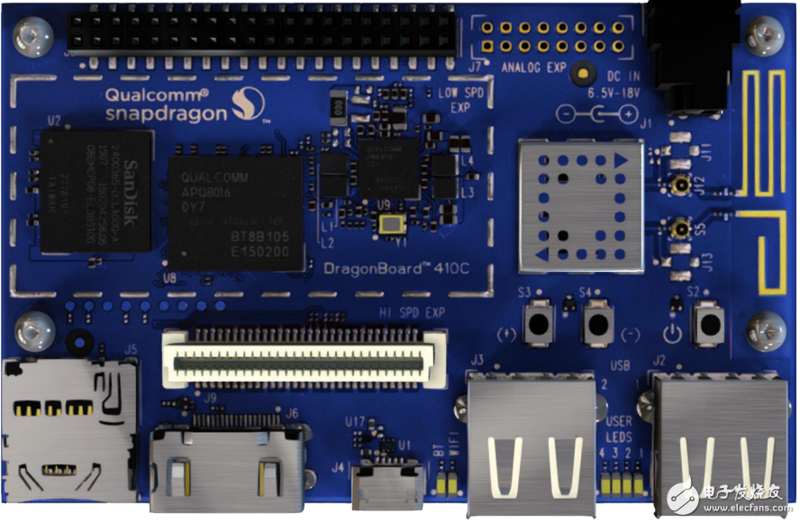
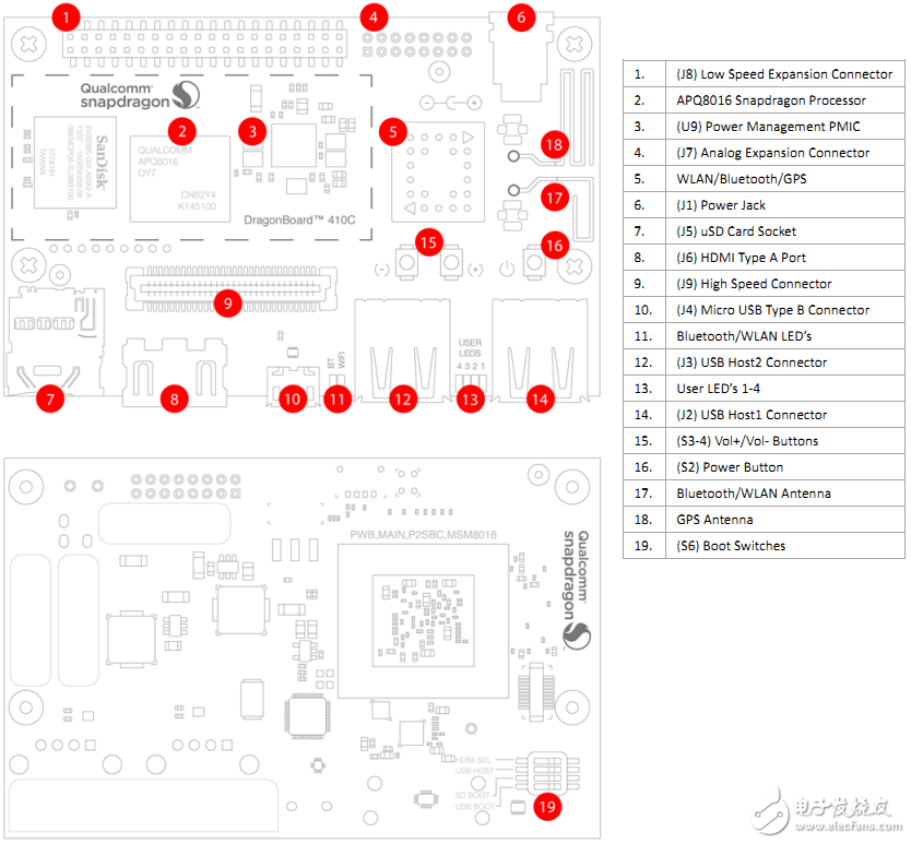
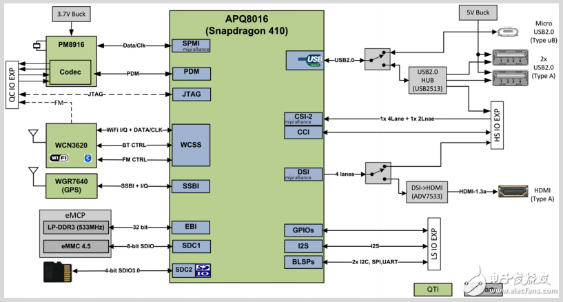
Qualcomm Opteron 410 processor APQ8016 has four 64-bit ARM Cortex-A53 MPcore Harvard superscalar core, supports LP-DDR2 or LP-DDR3 SDRAM interface, integrates Hexagon QDSP6 DSP, integrates Adreno 306 graphics processing unit, supports 13 million pixels Input, support 1080p video codec, integrated gpsOneGen 8c, BT4.1, support OpenGL ES 3.0, support DirectX, OpenCL, Renderscript calculation engine and FlexRender dynamic rendering technology.
2.3 StorageThe 410c integrates an embedded multi-chip package (eMCP) that includes 1GB LPDDR3 and 8GB solid state memory cells.
- LPDDR3, 32-bit bandwidth bus directly connected to the APQ8016's built-in LPDDR controller. Maximum DDR clock 533MHz
- eMMC, 8-bit bus directly connected to APQ8019 SDC1 interface, supports eMMC 4.5 specification
2.4 External SD cardThe 96Boards specification requires a microSDHC card holder on the board. The signal line of the uSD card of the 410c board is directly connected to the SDC2 interface of the APQ8016. The push-push card holder supports dedicated signal detection.
2.5 WIFI/BT/RFThe 96Boards specification requires WIFI (at least 802.11g/n) and Bluetooth4.1 (Bluetooth Low Power) on the board. Qualcomm's RF transceiver WCN3620 is used on the 410c. The WCN3620 integrates three different wireless connection technologies:
- WLAN, compatible with IEEE 802.11b/g/n specifications
- Bluetooth, compatible with BT specification version 4.1
- Global FM radio, optional extra configuration, unofficial support
2.6 display interface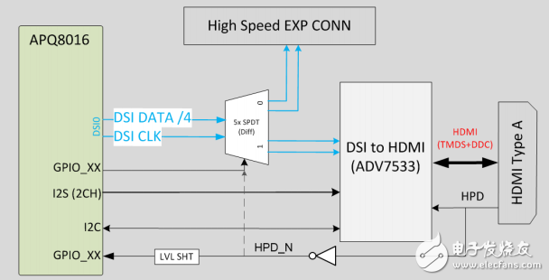
The 96Boards specification requires an HDMI interface on the board. The APQ8016 does not have a built-in HDMI interface output. The 410c uses the built-in MIPI-DSI 4lane output to connect to an external DSI to HDMI bridge chip, and the final output is 480i to 1080p HDMI signal.
2.8 MIPI-DSI interfaceThe 96Boards specification requires an MIPI-DSI output, and 410c leads to 4 lane MIPI-DSI via a high-speed expansion interface.
2.9 Camera interfaceThe 96Boards specification requires two camera interfaces. The 410c has two camera interfaces, a 4-lane MIPI-CSI interface and a 2-lane MIPI-CSI interface.
2.10 USB interface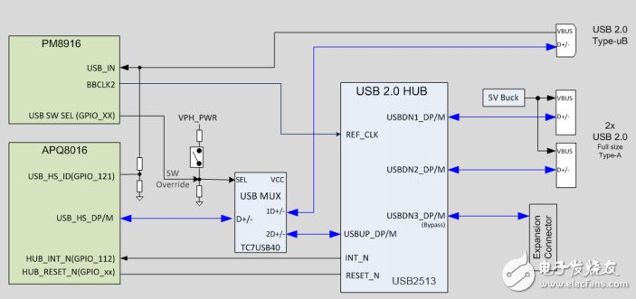
The 96Boards specification requires three USB host interfaces. The APQ8016 has only a single USBOTG channel. A total of three USB ports, one USB host and two USB devices are connected through an external multiplexer and USB Hub. Note that the USB host interface and USB device interface cannot be used at the same time.
3.1 AudioThe 96Boards specification requires at least single channel audio to be output via Bluetooth or HDMI/MHL/DisplayPort. The 410c meets 96board requirements and has additional audio channels.
3.2 DC power supply and batteryThe 96Boards specification requires the following solutions for system power supply:
- A 8V to 18V power supply from a dedicated DC interface
- A 5V USB TYPE C interface
- An 8V to 18V supply is introduced from the low speed expansion interface SYS_DCIN pin
Power management block diagram
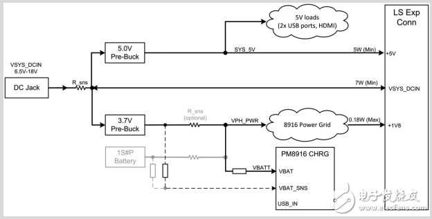
The 96Boards specification requires two buttons, a power/sleep button and a reset button.
3.4 System and User IndicatorsThe 96Boards specification requires at least six buttons, while the specification also defines the color of the LEDs and the position on the board. There are six indicators on the 410c.
Two system operation indicators:
- Wifi running indicator
- BT running indicator
Four user-defined lights
3.5 GPSThe GPS on the 410c is implemented by the Qualcomm WGR7640 GNSS RF Receiver, which supports GPS and GLONASS.
4.1 Additional power supply- +1.8V max 100mA
- +5V output at least 1A current
- SYS_DCIN 9~18V input, ensuring sufficient current to support system operation, or DCIN on board provides at least 7W.
The 410c board supports the following requirements:
+1.8V: driven by two PMIC LDOs, providing 55mA
+5V : driven by 4A 5.0V switching power supply
SYS_DCIN: Can be used as the main power supply on the board or from the board
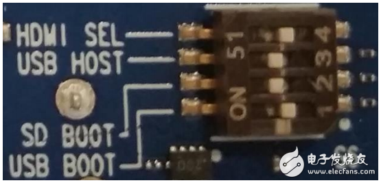
4.2 Startup configurationThere are 4 DIP switches on the 410c marked with S6. In order to ensure the normal operation and start of the system, you need to turn the four buttons to the off position.
Switch1, 'USB BOOT', when dialed to the 'on' position, will force the boot from the USB interface connected to the PC.
Switch2, 'SD BOOT', when dialed to the 'on' position, will be forced to boot from the uSD card.
Switch3, 'USB HOST', when dialed to 'on' position, USB HOST mode will be turned on, and OFF will turn on USB DEVICE mode.
Vertical-Cavity Surface-Emitting Lasers
Vertical-Cavity Surface-Emitting Lasers,Vertical External Cavity Surface Emitting Laser,Vertical Cavity Laser,Vertical Emitting Cavity Surface Laser
AcePhotonics Co.,Ltd. , https://www.cgphotonics.com