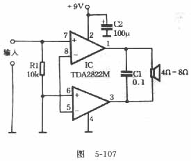
Generally, the integrated circuit has many peripheral components and requires a large heat sink. The power amplifier circuit introduced in this article is simple and easy to make. The circuit is shown in Figure 5-107. Using a TDA2822M power amplifier integrated circuit to connect to BTL mode, the peripheral components have only one resistor and two capacitors, no need to install a heat sink, and the playback effect is also satisfactory.
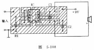
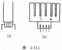
Please note when using: Because this power amplifier is directly coupled, the input signal must not have a DC component. If the input signal has a DC component, a capacitor of about 10uF must be connected in series at the input end, otherwise a large DC current will flow through the speaker, causing it to burn and burn. In practice, if the appropriate changes are made to Figure 5-107, the effect is more ideal. The improved circuit is shown in Figure 5-109. In use, it was found that the TDA2822M was hot when the volume was turned to the maximum, so a radiator was made for the TDA2822M, as shown in Figure 5-110. The radiator is made of aluminum sheet with a thickness of lmm, a length of 38mm, and a width of 25mm. And open 5 to 6 slots with a length of 10mm and a width of 1mm on the heat sink, and then fold the heat sink along the dotted line into a "mouth" shape. When installing the radiator, put some silicone grease on the TDA2822M (the silicone grease can be cut into the 3AX31 or 3AX81 tube shell). According to Figure 5-111 (a), it can be tied tightly with a thin wire. It should be noted that the pin number of TDA2822M is written on the side of the heat sink to avoid errors during soldering. After the radiator is added, the volume is turned to the maximum radiator and only a little warmer, the heat dissipation effect is good. This method can also be used for heat dissipation of other small integrated circuits. We use two power amplifier circuits to make a walkman stereo power connector to promote two small speakers, and the effect is very good.
|

Follow WeChat

Download Audiophile APP

Follow the audiophile class
related suggestion
The circuit diagram of the battery car charger is based on the characteristics of the electric bicycle lead-acid battery. When it is 36V / 12AH, the voltage limiting constant current charging method is used ...
The inverter introduced here (see picture) is mainly composed of field effect transistors and common power transformers. Its output power depends on the MOS FET and the power supply ...
