ADAS is becoming an integral part of the car – its interface can be connected to many different clusters of automotive electric/electronic systems. Similar to the human body, this requires a lot of functions and networking of these functions: sensors such as cameras, radar and ultrasound, as well as processing units and actuators. Given the complexity of the usage scenarios and the different vehicle areas where information must be exchanged, the importance of adequate network infrastructure for system efficiency is self-evident. From a functional point of view, driver assistance systems have begun to expand the range of traditional infotainment systems.
This article refers to the address: http://
As shown in Figure 1, "Evolution of Electric/Electronic Architecture," the driver assistance field is becoming an integral part of the electric/electronic ecosystem. ADAS and infotainment systems will evolve in the future.
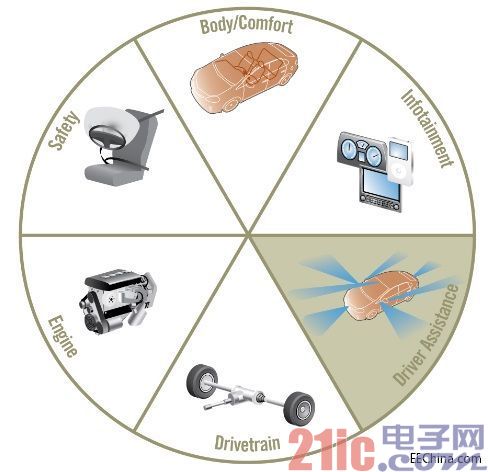
Figure 1: Evolution of the electric/electronic architecture
Typical emerging driver assistance applications include:
- parking assistance
- Collision warning
- Traffic sign monitoring
- Lane departure warning
- Advanced lane guidance
- Pedestrian warning
- night vision
- Adaptive cruise control
- Pre-crash warning
Driver assistance systems have special requirements for the network.
Features include:
- Transmission of control, video, data packets and IP data
- The highest quality service
- Hard real-time determinism and low latency
- Flexible topologies such as star, daisy chain and ring
- High bandwidth
- Remote control function
- Security aspects
- Stability and maturity
In addition to the items listed above, cost efficiency is also a key indicator.
Multi-channel solution
Typically, the driver assistance system must handle various sensor data. To cope with this complexity, it is often necessary to find a layered approach with different levels of abstraction and timing constraints. There is a large amount of raw data in the low level, which requires higher bandwidth and consistent and fast transmission. The middle level needs to transfer objects and attributes. Finally, the highest level will give the parsed data. A typical mapping of MOST technology is shown in Figure 2, "MOST Technology Data Transfer Mechanism".
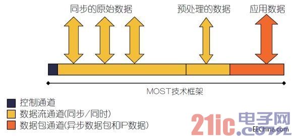
Figure 2: MOST technology data transmission mechanism
A multi-channel network system can use all services including control data, stream data, and packet data in parallel through one network. These services can be easily synchronized in a very certain way, if necessary.
The 3rd generation MOST specification introduces a MOST technology network with a speed of 150 Mbps. This network supports IP data communication and provides an automotive-ready Ethernet channel compliant with the IEEE 802.3 standard. The channel bandwidth can be freely configured from 0 to nearly 150 Mbps. MOST technology is open to a variety of IP-based applications, including seamless integration of wireless mobile devices and car-to-vehicle and car-to-infrastructure communications.
The MOST technology framework and functional module concept include a clear application programming interface that standardizes the driver-assisted application and sensor interface for cameras.
Flexible star topology for camera system integration
Figure 3 shows a multi-camera system based on the MOST150 network, which includes four high-definition cameras. Up to 150 Mbps of bandwidth can be allocated for each camera's video stream. The entire data stream bandwidth of the MOST 150 can be used separately for each camera link. The camera system can be expanded to eight cameras for a total of 1.2 Gbps of data stream bandwidth. The surround camera is connected to the central node of the star topology via a coaxial cable.
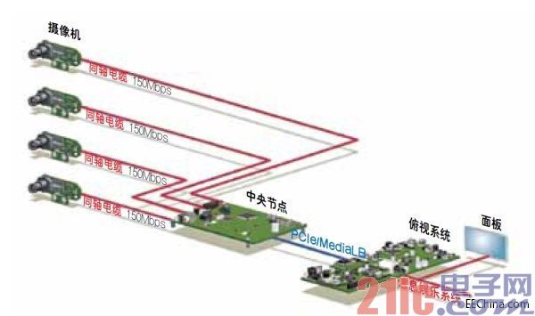
Figure 3: Multi-camera system based on MOST technology network
The 360-degree car overhead system (Figures 4 and 5) uses a small camera with a MOST technology interface that provides resolution of one megapixel and high dynamic range. Based on a cost-effective design, these cameras consist of an image sensor chip and a MOST technology interface chip. With remote control, the camera can be operated without a memory chip or an additional microcontroller.
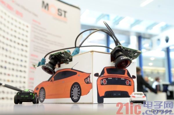
Figure 4: Overhead demonstration system based on MOST150 coaxial cable
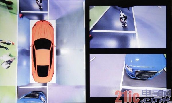
Figure 5: Top view
Thanks to the inherent synchronism brought by the TDMA mechanism, the MOST technology multi-channel network solution ensures real-time determinism and ultra-low video latency (less than 10 ms), so it can fully meet the needs of ADAS.
The MOST150 technology has been validated by a corresponding study with the German TUV. According to IEC 61508 and ISO 26262 standards, MOST150 has a security layer concept for fail-safe applications.
Multiply the bandwidth of multiple MOST150 branches
The network interface controller at the central node has multiple ports that can allocate up to 150 Mbps of data stream bandwidth for each network branch. Different branches can be built using any topology, including star, ring, tree, or daisy chain, and can be hot swapped or disconnected without affecting the flow of data from other parts of the system.
Low latency data stream
Sending a video stream from the camera to the renderer means that a large amount of video data will be transferred over a long period of time. Continuously transmitted data streams cannot be interrupted or have a delay. MOST technology transmits data streams by guaranteeing bandwidth and ultra-low latency. It does not require additional communication processor or addressing overhead, nor does it have a process of wasting bandwidth by splitting the data into multiple packets (therefore a packet needs to be checked each time the packet passes through the path).
Coaxial cable
With coaxial cable, this solution enables two-way communication and powering through the same cable, thus providing a scalable electrical physical layer for the ADAS automotive sector. Coaxial cable is the industry standard cable for transmitting high frequency signals. It provides shielding itself and is a low cost standard cable and connector. It features an automated connector structure that enables lower assembly costs compared to shielded copper twisted pairs. The coaxial solution is EMC-validated and operates at speeds up to several Gbps, making it a future-oriented physical layer.
Camera design
Figure 6 shows a block diagram of the camera module. The image sensor is directly connected to the MOST interface. The camera is controlled by I2C and GPIO and utilizes remote control functions. The video data is sent to the MOST interface and then transmitted over the MOST network with the highest quality of service.
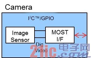
Figure 6: Camera block diagram
Remote control function
The camera module takes advantage of the new remote control features added to the MOST specification. This new feature reduces the software stack, which typically requires the use of microcontrollers and memory in peripheral nodes such as displays and cameras. For example, the remote control function supports the control port used as the I2C bus master. The I2C bus master manages the read and write operations of the image sensor and other on-board slaves, if any. I2C read and write operations are remotely processed through the MOST control channel. In addition, GPIO also remotely processes the channel through MOST technology. For example, they can be used as reset pins in a camera. GPIO events will be automatically reported via the MOST network. The existing processing power in the electrical control unit (ECU) overlooking the system is used to run control software for all cameras.
Centralizing all control software into the ECU of the overhead system significantly simplifies the development process, since only one software instance needs to be developed and deployed in this case. This device architecture helps optimize system partitioning, save board space, and even reduce power consumption in remote devices.
Stability and maturity
Today, MOST technology has been proven to be stable in 150 models on the road. Cars using the latest MOST150 network have also been on the road since 2012.
MOST technology provides a cost-effective system solution method for ADAS. The main advantages are as follows:
- Deterministic and ultra-low latency through TDMA mechanism
- MOST's data stream feature supports continuous transmission of video data streams without data packing or buffering
- The highest quality service
- Support multiple data types: control, data packets, data streams and IP data
- Flexible topologies such as star, daisy chain and ring
- Proven vehicle coaxial physical layer
in conclusion
This paper demonstrates that the MOST technology network provides the best solution for camera systems such as overhead systems. The multi-channel network solution supports parallel transmission of control packet data such as control messages, video data streams, and object lists. The flexible framework supports both star and ring topologies and a mix of the two. The data flow characteristics of MOST technology are based on the TDMA mechanism, which supports real-time data streams and provides ultra-low latency and highest quality services. MOST technology can allocate up to 150 Mbps of bandwidth for each camera's data stream. In a ECU of a top view system, when using a star architecture consisting of eight cameras, up to 1.2 Gbps of bandwidth can be used to transmit video to the central processor. data. This technology uses proven automotive coaxial cables and connectors and can be powered from the same cable. MOST technology has been used in more than 150 types of vehicles on the road, providing a stable and mature choice for camera systems.
The stepping motor is an induction motor. Its working principle is to use electronic circuit to supply power when the DC power is changed into components. The multi-phase timing control current is used to supply the stepping motor with this current, and the stepping motor can work normally. The driver is the time-division power supply for the Stepper Motor, multi-phase timing controller.
Step motor,Stepper motor,Small stepper motor,Micro stepper motor,Geared stepper motor,High torque stepper motor
Shenzhen Maintex Intelligent Control Co., Ltd. , https://www.maintexmotor.com