0 Preface
The micro-injection pump is a long-term micro-injection instrument that is often used in clinical medicine and life science research. This instrument is mainly used in arteriovenous infusion, blood transfusion, and precision chemical experiments. At present, the main problem of micro-injection pumps at home and abroad is that the accuracy is not high, and generally only single-channel uniform speed injection is achieved. In some cases, such as food detection chromatographic analysis, uniformly variable injection reagents are often required. Therefore, it is necessary to design a uniform acceleration or deceleration syringe pump, and control multiple syringe pumps in conjunction with each other to realize the data processing of human-machine dialogue.
1 System Overview
As shown in Figure 1, the system can be divided into 4 modules, including computer software control module, main control chip module, stepper motor drive module, and sensor module.

The computer is connected to the main control chip module through the RS 232 serial port. Through the self-designed monitoring software, the working state of the syringe pump can be monitored and managed in real time. After operation, it can be fully automated. The main control chip module is composed of ARM and FPGA and peripheral circuits. The FPGA generates the electrical pulse signal required by the stepper motor and transmits it to the driver module. The pulse distributor in the driver module distributes the electrical pulse signal to each phase of the motor in a prescribed manner Excitation winding to drive the rotor of the stepper motor. At the same time, the incremental rotary encoder and pressure sensor installed on the motor shaft monitor the actual working situation of the motor in real time. Due to the real-time processing characteristics of FPGA, the sensor data will be synchronously transmitted to the FPGA when the rotary encoder has stopped Encoding, and when FPGA sends a pulse signal, it will immediately stop the motor and beep to alarm, and enter the locked-rotation state; when the pressure measured by the pressure sensor exceeds the maximum pressure, the motor will be stopped immediately, and the computer prompts and beeps Call the police.
2 Hardware design
2.1 Main control chip module
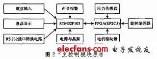
As shown in Figure 2, the main control module uses a combination of ARM and FPGA. The ARM embedded processor is mainly responsible for man-machine interface and external communication and manages the overall process. The FPGA implements parallel control of multiple stepping motors and real-time processing of sensors. Its peripheral circuits include: LCD module, keyboard input module, power module, RS 232 interface conversion module, alarm module.

ARM adopts the STM32F103 processor based on the ARMCorrex M3 core introduced by STMicroelectronics (ST). It integrates 32-bit RISC processor, low power consumption, high-performance analog technology, high-speed DMA channel, rich on-chip peripherals, and JTAG emulation debugging. In terms of performance, the CorrexM3 core adopts the ARM V7 architecture, the instruction speed can be close to 80 MIPS, and it has powerful data processing and computing capabilities.
FPGA (ie field editable gate array) uses the CYCLONE II series produced by Attera. EP2C5. FPGA uses a unique parallel computing circuit. Multiple control objects can be added to a control core for independent driving. The control performance is not affected, and there is no interference between the control objects, which avoids the tedious timing design problems in multi-object real-time control. , Just meet the requirements of the design to control multiple injection pumps at the same time, to a certain extent improve the system integration and anti-interference ability. At the same time, FPGA has hardware real-time processing capability. Each hardware is instantiated in FPGA. Equivalent to rotary encoder and pressure sensor have become a hardware block of FPGA. Therefore, its processing speed will be very fast.
The triode, the full name should be a semiconductor triode, also known as a bipolar transistor, a crystal triode, is a semiconductor device that controls current. Its function is to amplify the weak signal into an electrical signal with a large amplitude value, and also as a non-contact switch.
Transistor is one of the basic components of semiconductors, with current amplification, is the core component of electronic circuits. The triode is made up of two closely spaced PN junctions on a semiconductor substrate. The two PN junctions divide the monolithic semiconductor into three parts, the middle part is the base area, and the two sides are the emitter area and the collector area, and the arrangement is PNP. And NPN two.
Small Signal Transistor,Digital Transistor,Darlington Transistor,Power Transistor
Dongguan Agertech Technology Co., Ltd. , https://www.agertechcomponents.com