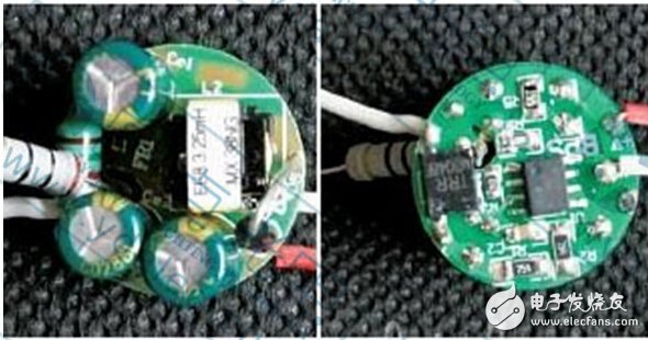
It is often said that the short life of LED lamps is mainly due to the short life of the power supply, and the short life of the power supply is due to the short life of the electrolytic capacitor. These arguments also have some truth. Because the market is flooded with a large number of short-lived and inferior electrolytic capacitors, and now they are fighting for the price, some manufacturers have adopted these inferior short-life electrolytic capacitors regardless of the quality. The result is the above conclusion.
So what is the actual situation?
1. The life of an electrolytic capacitor depends on the ambient temperature at which it operates.
How is the life of an electrolytic capacitor defined? Of course it is defined in hours. However, if the life index of an electrolytic capacitor is 1,000 hours, it does not mean that the electrolytic capacitor will be broken after a thousand hours. No, it just means that the capacity of this electrolytic capacitor is reduced by half after 1000 hours. Originally, the capacity was reduced by half. It is 20uF, and now it is only 10uF.

In addition, there is another characteristic of the life index of the electrolytic capacitor, which is to indicate the life in the case of how many degrees of working temperature. And usually it is specified as the life at 105 ° C ambient temperature.
This is because the electrolytic capacitors we use today are electrolytic capacitors using liquid electrolyte. If the electrolyte is dry, the capacitance is of course gone. The higher the temperature, the easier the electrolyte will evaporate. Therefore, the life indicator of the electrolytic capacitor must indicate the life at what ambient temperature.
So all current electrolytic capacitors are marked with a lifetime at 105 °C. For example, the most common electrolytic capacitor has a life of only 1,000 hours at 105 °C. But if you think that all electrolytic capacitors have a life of only 1,000 hours. That's a big mistake.
Simply put, if the ambient temperature is higher than 105 ° C, its life will be less than 1,000 hours, if the ambient temperature is lower than 105 ° C, then its life is higher than 1,000 hours. So is there a rough quantitative relationship between life and temperature? some!
One of the simplest and easy to calculate relationships is that for every 10 degrees increase in ambient temperature, life is reduced by half; in turn, for every 10 degrees decrease in ambient temperature, life expectancy is doubled. Of course this is just a simple estimate, but it is also quite accurate.
Because the electrolytic capacitor used for the LED driving power supply is definitely placed inside the LED lamp housing, we only need to know the internal temperature of the LED lamp to know the working life of the electrolytic capacitor.
2. What is the ambient temperature in the LED fixture?
Because LEDs and electrolytic capacitors are placed in the same housing in many fixtures, the ambient temperature is simply the same. This ambient temperature is mainly determined by the balance of heat and heat dissipation between the LED and the power supply. And the heat and heat dissipation of each LED luminaire is different, so how can we know the ambient temperature?
In fact, this problem can be reversed, that is, a well-designed LED luminaire, which allows the internal ambient temperature to be constant. This is because the junction temperature of the LED chip is the main reason for determining the light decay (life) of the LED chip. The LED junction temperature is of course related to its ambient temperature, so as long as the allowed LED junction temperature is known, it can be inferred from the inside of the LED fixture. Ambient temperature.
However, there are at least three thermal resistances, that is, the thermal resistance θjc of the LED chip to the outer casing, and the thermal resistance of the LED casing to the surface of the aluminum substrate. In fact, it passes through the solder, the copper foil, and the insulating layer to the aluminum plate, but among them The most important is the thermal resistance of the insulating layer, collectively referred to as θlv, and the third is the thermal resistance θla of the air from the aluminum plate to the blister.
Take the 3014 LED, its thermal resistance θjc is 90 ° C / W, because its power is only 0.1W, so the internal and external temperature difference is 9 ° C. The thermal resistance of the aluminum substrate is 1 ° C / W. For a 10 W luminaire, since all 10 W LEDs are mounted on the same aluminum substrate, the total temperature difference is 10 ° C, a total temperature difference of 19 ° C, the last Θla is difficult to estimate because it is related to the circulation of air. In the case where the internal air does not flow, the temperature difference is only about 1 °C, so the total is 20 °C. That is, the LED junction temperature is equal to the ambient temperature plus 20 °C.
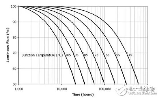
So can the ambient temperature inside the bulb allow 105 degrees? Just look at the picture below and you will know. That is the relationship between Cree's LED chip junction temperature and light decay.

If the ambient temperature is 105 ° C, then at least 20 ° C is the junction temperature, so the junction temperature is about 125 ° C. It has not been found on this curve and can only be roughly estimated to have a lifetime of only 4,000 hours. This is absolutely unacceptable! In other words, the ambient temperature in the LED bulb must be much lower than 105 °C!
Product Description
SPD Surge Protective Device,Lightning Surge Protector
Surge Protection Device (SPD)
It is a device used to limiting instant surge voltage and discharge surge current, it at least including a non-linear component.
Surge protective Device Model Selection
With the impact of international information flow, the rapid development of microelectronic science and technology, communication, computer and automatic control technology, make the building start to go for high quality, high functional area, formed a new building style-intelligent building. As inside the intelligent building there are lot of information system, <
SPD essentially is a equipotential connection material, its model selection is according to the different lightning protection area, different lightning electromagnetic pulse critical and different equipotential connection position, decide which kind of SPD used in the area, to achieve the equipotential connection with the common earth electrode. Our statement will based on SPD's maximum discharge current Imax, continuous operating voltage Uc, protection voltage Up, alarm mode etc.
As per << Lightning Protection Norm>> item 6.4.4 stipulation "SPD must can withstand the expected lightning current flow and should confirm to the additional two requirements: the maximum clamp voltage during surge across, capable to extinguish the power frequency follow-on current after lightning current across." That is the value of SPD's max. clamp voltage add its induction voltage of two ends should be same with the system's basic insulation level and the equipment allowed max. surge voltage.
SPD for Power Supply System Series Selection Guide
The installation of SPD at each lightning protection zone, according to the standard of low voltage electrical appearance, make classification of electrical equipment in accordance with the over voltage category, its insulation withstand impulse voltage level can determine the selection of SPD. According to the standard of low voltage electrical appearance, make classification of electrical equipment in accordance with the over voltage category as signal level, loading level, distribution and control level, power supply level. Its insulation withstand impulse voltage level are:1500V,2500V,4000V,6000V. As per to the protected equipment installation position different and the different lightning current of different lightning protection zone, to determine the installation position of SPD for power supply and the break-over capacity.
The installation distance between each level SPD should not more than 10m, the distance between SPD and protected equipment should as short as possible, not more than 10m. If due to limitation of installation position, can't guarantee the installation distance, then need to install decoupling component between each level SPD, make the after class SPD can be protected by the prior class SPD. In the low voltage power supply system, connecting an inductor can achieve the decoupling purpose.
SPD for power supply system specification selection principle
Max. continuous operating voltage: bigger than protected equipment, the system's max. continuous operating voltage.
TT System: Uc≥1.55Uo (Uo is low voltage system to null line voltage)
TN System: Uc≥1.15Uo
IT System: Uc≥1.15Uo(Uo is low voltage system to line voltage)
Voltage Protection Level: less than the insulation withstand impulse voltage of protected equipment
Rated discharge current: determined as per to the lightning situation of the position installed and lightning protection zone.
SP1 Series
Normal Working Conditions
-Altitude not exceed 2000m
-Ambient air temperature:
Normal range: -5ºC~+40ºC
Extend range: -40ºC~+80ºC
-Relative Humidity: 30% - 90% under indoor temperature condition
- At the place without obviously shaking and shock vibration
- Non-explosion danger medium, non-corrosion gas and dust ( including conductive dust)
Classification
-As per Nominal Discharge Current:
5,10,20,30,40,60KA(8/20µs)
- As per Maximum continuous operating voltage:
275V,320V,385V,420V,440V,460V
- As per to poles
1P,1P+N,2P,3P,3P+N,4P
- As per auxiliary functions:
a. With remote signal output ( remote alarm function)
b. Without remote signal output
Selection Principle
- The continuous applied voltage on the two terminals of SPD should not more than the maximum continuous operating voltage Uc value;
- The voltage protection level Up of SPD should less than the maximum impulse withstand voltage of the protected equipment;
- As per to the different earthing system and protection mode to select the specification accordingly;
Product Features
1, built-in over-current overheating, temperature control circuit technology.
2, the module design, easy installation, online replacement.
3, low leakage current, fast response time, low residual voltage.
4, alarm indication device, green (normal) v red (fault).
| Model/Technical Parameters | WR-B60 | WR-B80 | WR-B100 | WR-B120 | WR-B150 |
| Rated Operating Voltage Un (V ~) | 220V 380V | 220V 380V | 220V 380V | 220V 380V | 220V 380V |
| Maximum Continuous Operating Voltage Uc (V ~) kV | 385V 420V | 385V 420V | 385V 420V | 385V 420V | 385V 420V |
| Voltage Protection Level Up (V ~) kV | ≤1.8≤2.2 | ≤2.4≤2.5 | ≤2.5≤3.2 | ≤3.4≤3.7 | ≤4.0≤4.5 |
|
Maximum Discharge Current Imax(8/μ20μs)kA |
60 | 80 | 100 | 120 | 150 |
|
Nominal Discharge Current In(8/μ20μs)kA |
30 | 40 | 60 | 80 | 100 |
| Response Time | <25 | <100 | |||
| L/N(mm²)The Cross Section Of L/N Line | 16,25 | 16,25 | 16,25 | 16,25 | 25,35 |
| PE (mm²)The Cross Section Of PE Line | 16,25 | 25,35 | 25,35 | 25,35 | 35 |
| Fuse or Switch (A) | 63A | 63A | 63A,100A | 63A,100A | 63A,125A |
| The Line Section of Communication and Alarm (mm²) | ≥ 1.5 | ||||
|
Operating Environment-C |
(-40ºC~-+85ºC) | ||||
| Relative humidity 25 ºC | ≤95% | ||||
| installation | Standard Rail35mm | ||||
| Material of Outer Covering | Fiber Glass Reinforced Plastic | ||||
Surge Protector SPD,Surge Protection Device SPD,SPD
Wenzhou Korlen Electric Appliances Co., Ltd. , https://www.zjthermalrelay.com