As a tool for precision measurement, grating has been widely used in the fields of precision instruments, coordinate measurement, precise positioning, high precision precision machining, etc. due to its own advantages. The grating measurement technique is based on the moire fringe signal formed by the relative movement of the grating. A series of processing is performed on the signal to obtain the displacement of the relative movement of the grating. The grating displacement sensor is combined with microelectronic technology to measure the linear displacement to achieve high measurement accuracy. In this paper, the grating is used as the sensing element, and after receiving the component, it becomes a periodically changing electrical signal (approximate sinusoidal signal). The logical discriminating circuit is used to distinguish the forward and reverse of the displacement, and the data processing is performed by the single chip microcomputer and the result is displayed. The software is implemented in assembly language.
1 hardware circuit
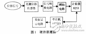
The hardware circuit of this design is mainly composed of single chip microcomputer 89C51, counter 8253, subdivision and discrimination circuit, signal conversion circuit and grating displacement sensor. As shown in Figure 1.

1.1 grating displacement sensor
The grating displacement sensor comprises the following parts: a grating; a grating optical composition. The function of the grating optical system is to form moiré fringes; a photoelectric receiving system. The photoelectric receiving system is composed of a photosensitive element, which converts the optical signal of the moire fringe into an electrical signal, and the photosensitive element used in the system is four silicon photo cells.
1.2 signal conversion circuit
The signal transformation is to convert the sinusoidal electrical signal output by the photosensitive element into a square wave signal. In this paper, the comparator LM339, the moire fringe from the grating is applied to the photosensitive element silicon photocell, and the electrical signal they output is applied to the positive input terminals of the two comparators of the LM339, and the two comparators are The negative input terminal prefabricates a certain reference voltage, and the reference voltage should make the square wave of the grating output have the same height and low level width.
1.3 Subdivision and discrimination circuit
1.3.1 Subdivision circuit
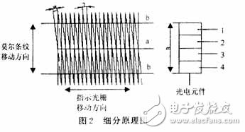
In order to record the number of stripes moved over the grating and determine the movement rate of the grating, etc., a 4-pole silicon photocell is used in the sensor to receive the moire fringe signal. Adjust the width B of the moiré strip so that it is exactly the same width as the four silicon photocells. Then, four signals having a phase difference of 90° in phase can be directly obtained, that is, four times of subdivision is performed. as shown in picture 2.

1.3.2 Discriminating circuit
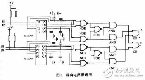
In addition to the size attribute, the displacement has a direction attribute. In order to discern the direction of the scale grating displacement, it is not possible to output a signal by only one photosensitive element. There must be more than 2 signals to determine the direction of displacement based on their phase differences. Therefore, the design uses four silicon photocells to receive the moire fringe signal, and the output four signals are sequentially different by 90° in phase. The discriminating circuit designed by using this feature is shown in FIG. In the figure, u1, u2 and u3, u4 respectively realize the difference in the direction of displacement by the same circuit. When the moiré fringes move up (assuming the first two of the silicon photocells, u1, u2 have signals, u3, u4 have no signal), then point A has a counting pulse, and point B is a constant level; When the stripe is moved down (assuming the first two of the silicon photocells, u1, u2 have signals, u3, u4 have no signal), there is a counting pulse at point B in the figure, and point A is a constant level. Discrimination can be achieved by recording the number of pulses formed by up and down shifts with two different counters.

1.4 LED display
This article uses a dynamic 4-bit display. The first bit is the symbol, the moire fringe is shifted up to positive, the downshift is negative; the second and third bits are integer bits; the fourth bit is decimal place. All the segment selection lines are connected in parallel, controlled by the P1 port of the single chip microcomputer, and the common cathode common terminal is controlled by P3.0, P3.1, P3.2, P3.3, respectively, to realize the time division gating.
2 software part
The software part mainly consists of collection subroutine, data processing and display subroutine.
The acquisition subroutine completes the reading and conversion of the count value; the data processing subroutine completes the linearization processing of the collected data; and displays the subroutine to cyclically display the result. The flow of the program is shown in Figure 4.

3 Conclusion
In this paper, the designed hardware uses the comparator LM339 to convert the output signal of the photosensitive device into a square wave signal, and uses the logic discriminating circuit to make an accurate judgment on the forward and reverse movement of the grating; the two counters of the 8253 are respectively aligned. The counter two signals are counted, and then the data is processed by the 89C51 and sent to the display. The hardware structure is simple, the cost is low, the work is reliable, and the precision is relatively high; the software is implemented in assembly language, the program is simple, the readability is strong, and the efficiency is high.
Compression Driver,Tweeter Driver Unit,Compression Driver Speaker,High Frequency Compression Driver
Guangzhou Yuehang Audio Technology Co., Ltd , https://www.yhspeakers.com