The main point of this production is to make a free Wifi waveguide antenna (although some self-provided materials are needed).
Routers commonly used to set up wireless networks use omnidirectional antennas to send and receive packets, and these signals are sent in all directions with the same strength. One of the more tragic things is that the antennas of ordinary routers are not powerful, and the range is only 50 to 100 feet.
The signal of the directional antenna is concentrated in a specific direction. Although the signal strength in other directions is sacrificed, a larger communication distance can be obtained in the required direction.
The disadvantage of the amplifier we mentioned last time is that the signal can only be enhanced in a small area near the focal point of the curved aluminum skin, and the effect is not as obvious as expected.
Another popular method is to use a colander. This method is used in many field operations. However, considering that not everyone has an idle colander, it is still recommended to use this method.
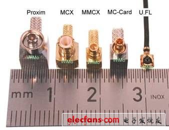
The metal tank antenna described below is designed to expand the communication range of a low-cost router. It is a directional antenna made of metal, which can be connected to the router body through a coaxial cable with an N-type connector.
1 Waveguide principle
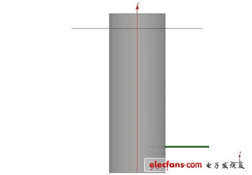
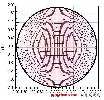
The metal tank antenna we are going to do is a channel that guides electromagnetic waves to a specified direction, and it is called a waveguide in professional terms. In the waveguide, the electromagnetic field can only exist in a specific mode. Only one mode is allowed in the best waveguides, because different modes are transmitted at different speeds in the waveguide, which will cause scattering and the pulse width of the signal will expand, making reception difficult. At the same time, different modes also have different radiation directions. The above shows a transverse electric field (TE) and a transverse magnetic field (TM) mode-the main modes in circular waveguides.
Let's take the TE11 mode as an example. This mode occupies a dominant position in the circular waveguide. Above is the side view of the waveguide and the feeder. The gray rectangle is the tank antenna, and the center conductor in the small green feed line extends into the tank. It is a quarter-wavelength away from the bottom of the tank, which excites the TE11 mode: the electric field is drawn in red and the magnetic field is drawn in blue.
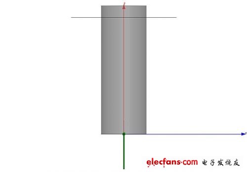
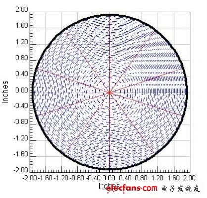
Now suppose you connect the feeder from the bottom of the pot antenna instead of near the bottom, which will stimulate another mode different from the above. This is called TM11 mode, the electric field is shown in red, and the magnetic field is shown in blue.
2 Parameter calculation
As mentioned above, only a single TE mode is expected to be excited in the waveguide antenna (this determines the need to adopt a design that extends from the tank wall into the feeder). For this, a suitable metal can can be selected. Its diameter is just to allow TE11 mode to be generated but TM01 mode can be disabled. Considering the frequency of the Wifi network used daily, most 802.11 networks, such as 808.11b / g use the 2.4GHz band, 808.11n use the 2.4 and 5GHz band, but the 2.4GHz signal is still strong when transmitting over long distances. For the sake of simplicity, only consider the 808.11b / g wireless network with a frequency band of 2.412 ~ 2.462Ghz. For this band, the TE11 mode can be excited at 2.412 GHz when designing the metal can antenna, and the TM01 mode will not be excited when working at 2.462 GHz.
If you want to solve it quickly, refer to this webpage, which has an online calculator to help you calculate the diameter of the jar and the position of the feeder.
Online calculator
Or you can take out the paper and pen to start the calculation:
The first is the proper diameter of the jar.
TE11 mode will be activated when f = 2.412GHz》 f_cutoff = 2 * c / (3.41 * D).
TM01 mode will not be activated when f = 2.462GHz << f_cutoff = 2 * c / (2.61 * D).
We need f_cutoffTE11 << f << f_cutoffTM01
This solves 2.87 inches "D" 3.67 inches
Generally speaking, the lower diameter limit here is more important. The jar needs to be larger than 2.87 inches to work effectively at 2.4G, and although the upper limit has some impact, it is not a hard limit on whether the antenna can work.
Next we need to calculate the position of the feeder.
As mentioned earlier, in order to excite the TE11 mode, the feeder should be placed at 1/4 wavelength, and the length of the entire pot antenna is 3/4 wavelength. In an open space, you only need to divide the speed of light c by the frequency to get the wavelength of the electromagnetic wave, but the internal situation of the pot antenna changes somewhat. The standing wave wavelength here needs to be calculated according to the following formula:

Therefore, from the diameter D of the can that meets the requirements, the remaining length 3 / 4Lg after the can is cut and the distance from the bottom of the can to 1 / 4Lg can be calculated. This is the result given by the online calculator.
Finally, when we introduce the feeder from the tank wall, the length Lo required by the metal conductor extending into the tank is 1/4 wavelength.
3 Required materials
Diesel Generator Power Range,Single Phase Diesel Generator,Mobile Type Diesel Generator,Standby Power Diesel Generator
Shanghai Kosta Electric Co., Ltd. , https://www.ksdpower.com