Abstract Electronic Control Unit (ECU) is synonymous with vehicle internal system control module. This paper describes how to integrate custom ECU and ECU products with SAEJI939CAN interface, realize the vehicle network based on SAE JI939 protocol, complete the information collection of custom ECU and exchange information between ECUs. The network uses dual-core single-chip microcomputer and μC/OS-II operating system to realize information interaction through liquid crystal display and buttons, which solves the problems of less information on vehicle dashboard and lack of real-time fault diagnosis. The method can be applied to similar CAN communication fields in other industrial environments, such as train control, factory control, and the like.
Keywords SAE JI939 protocol vehicle network integration method electronic control unit CAN
This article refers to the address: http://
Introduction As vehicles become more electronic and automated, ECUs on vehicles are increasing. In order to improve the utilization of signals, a large amount of data state information can be shared between different ECUs, and a large number of control signals can be exchanged in real time. In this way, traditional harnesses are far from meeting this need.
CAN bus and CAN-based vehicle network communication protocols provide a solution to the above problems. The SAE J1939 protocol is a heavy-duty truck and bus network communication protocol developed by the Society of Automotive Engineers (SAE) based on the CAN2.0B protocol. It is one of the most widely used application layer protocols in automotive electronic networks. The protocol uses multiplexing technology to provide standardized high-speed network connections based on the CAN bus for each sensor, actuator and controller of the vehicle, enabling high-speed data sharing between different ECUs to effectively reduce the number of harnesses and improve vehicle electronics. Control system flexibility, reliability, and maintainability.
At present, most of the vehicle's ECU products have SAE J1939 CAN interface. For ECU products with SAE J1939 CAN interface (such as engine, transmission and retarder and ABS ECU), customize several ECUs, integrate the vehicle network based on SAE J1939 protocol, complete the information collection of custom ECU and each ECU Information exchange between.
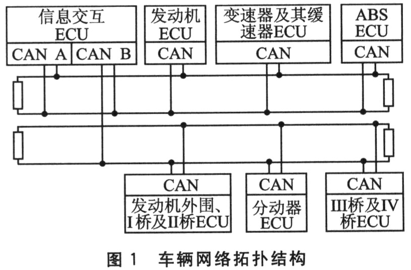
1 Vehicle network topology ECU products with SAE J1939 CAN interface are connected to the instrument panel and connected to the network, which has basically met the requirements of vehicle driving. In order to make the external communication of the custom ECU as far as possible does not affect the communication between the ECU products, the whole network is divided into two network segments, which can be combined into one network segment if necessary. Network segment A contains information interaction ECU, engine ECU, transmission and retarder ECU, ABS ECU; network segment B includes information interaction ECU, engine periphery, I bridge and II bridge ECU, transfer ECU, III bridge and IV bridge ECU. The information interaction ECU is connected to two network segments by two CAN ports, and has a message forwarding function. The vehicle network topology is shown in Figure 1.

2 Vehicle network communication design According to the SAE J1939 agreement, vehicle network communication design includes the following aspects:
â—† The physical layer is compatible with SAEJI939-11;
â—† The data link layer is compatible with SAE J1939-21;
â—† The network layer is compatible with SAE J1939-31;
â—† The application layer is compatible with SAE J1939-71;
â—† Application layer diagnostics are compatible with SAE J1939-73;
â—† Network management is compatible with SAE J1939-81.
2.1 Physical layer The physical layer implements the electrical connections of all ECUs on the network. The physical medium uses a shielded twisted pair with a characteristic impedance of 120 Ω, CAN_H is yellow, and CAN_L is green. The network segment uses a linear topology where possible, with a baud rate of 250 kbps. Both ends of the segment trunk are terminated with a 120 Ω resistor. The ECU uses short stubs to connect to the segment trunks and uses unequal arrangements in the segments to prevent standing waves.
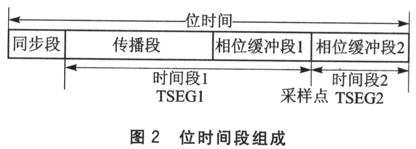
The bus management functions such as synchronization, network delay compensation and sampling point position determination in bit time are shown in Figure 2. The synchronization is the phase buffer segment 1 lengthening or the phase buffer segment 2 shortening, and the upper limit is the synchronous jump bandwidth (SJW). The sampling point is located as far as (but not exceeding) 7/8 of the bit time, which can achieve the best compromise between propagation delay and clock error. When the clock frequency is 16 MHz, the recommended division factor = 4, SJw = ltq, TSEGl = 13tq, TSEG2 = 2tq (tq is the clock period).

2.2 Data Link Layer The data link layer provides reliable data transmission on the physical layer and implements data exchange of application layer packets. Through the organization of the data link layer, functions such as synchronization, sequence control, error control, and flow control that the data frame must be transmitted are realized.
The data link layer organizes protocol related information in data frames through Protocol Data Units (PDUs). The PDU consists of a 29-bit ID and an O-8 byte data field in the data frame. The data structure is shown in Figure 3. The P field determines the priority of the message; the R bit is reserved; the DP bit is the data page bit; the PF field determines the PDU format (PDU1 or PDU2); the PS field is the PDU detail, and the PF field determines whether the target address DA or the PF, the group Expand GE; SA is the source address.

The packets provided by the data link layer include command packets, request packets, broadcast/response packets, response packets, and group function packets. In addition, the data link layer also implements a transport protocol function for packet reassembly and connection management of messages larger than 8 bytes, and is divided into a BAM protocol for broadcast announcements and an RTS/CTS protocol for peer-to-peer sessions.
2,3 Network layer The network layer defines the device requirements and services that provide interconnection functions between different network segments. The network interconnection ECU is required when multiple network segments exist, and its functions include packet forwarding, packet filtering, packet address translation, message reassembly, and database management. The network layer function is optional for a specific ECU, and only the information interaction ECU in the network uses the network layer function.
2.4 Application layer The application layer defines the signals (parameters) and messages (parameter groups) for vehicle applications. The application layer assigns a 19-bit suspicious parameter number (SPN) to each parameter through the parameter description signal; a 24-bit parameter group number (PGN) is assigned to each parameter group by the parameter group description message. The SPN is used to identify the parameters in the fault diagnosis element, component or parameter group associated with the ECU; the PGN is used to uniquely identify a particular parameter group. In addition to the assigned parameters and parameter groups, the user can supplement the application layer by assigning unused SPNs to custom parameters and defining proprietary messages.
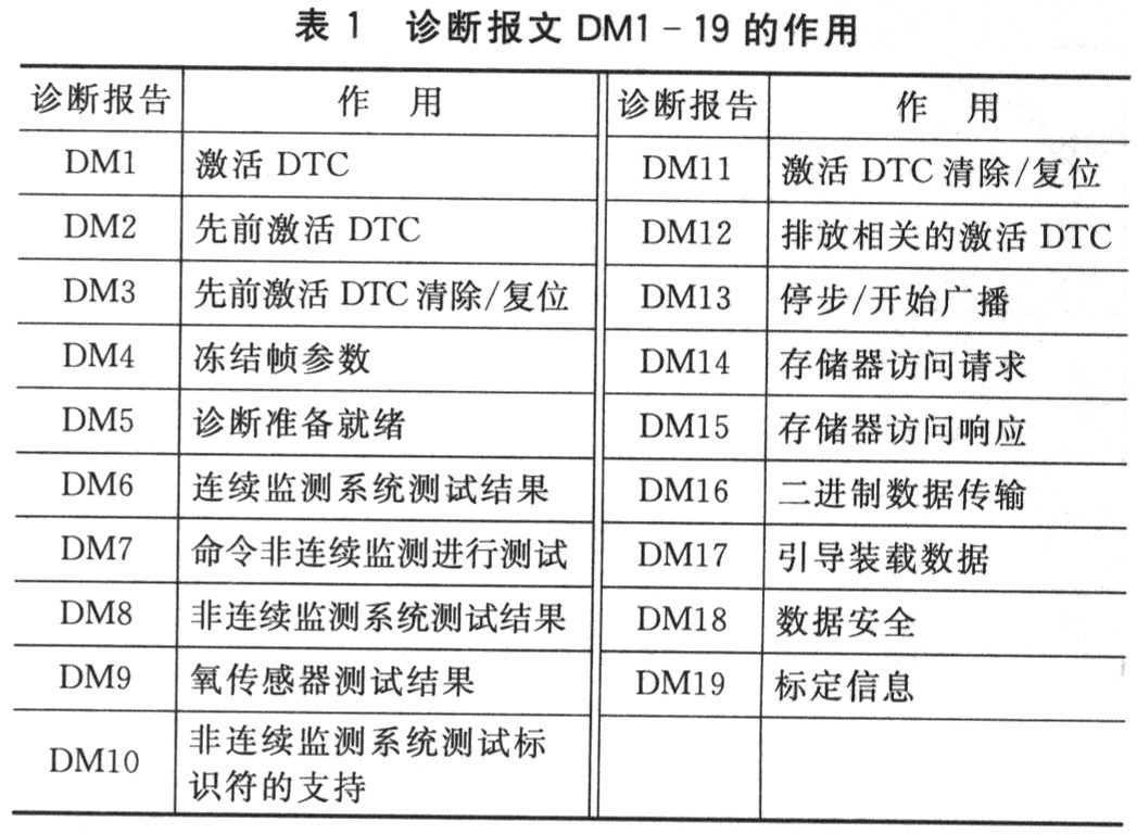
2.5 Application layer diagnostics The application layer diagnostics defines the diagnostic message DMl-19, whose role is listed in Table 1. These 19 messages are not available on the network. Currently, only the messages DM1, DM2, DM3, and DM11 are used in the network.

The diagnostic trouble code (DTC) in Table 1 is 4 bytes, consisting of 19-bit suspicious parameter number (SPN), 5-bit failure mode (FMI), 7-bit failure occurrence number (OC), and 1-bit SPN conversion mode (CM). ) composition, as shown in Figure 4.

2.6 Network Management Layer The network management layer uniquely identifies the controllers on the network by providing definitions and process descriptions of address assignment management and network error management. Its functions include: requesting the address and name of the controller on the network, declaring an address for the controller, an address that the announcement cannot declare, and commanding other controllers to use the new address.
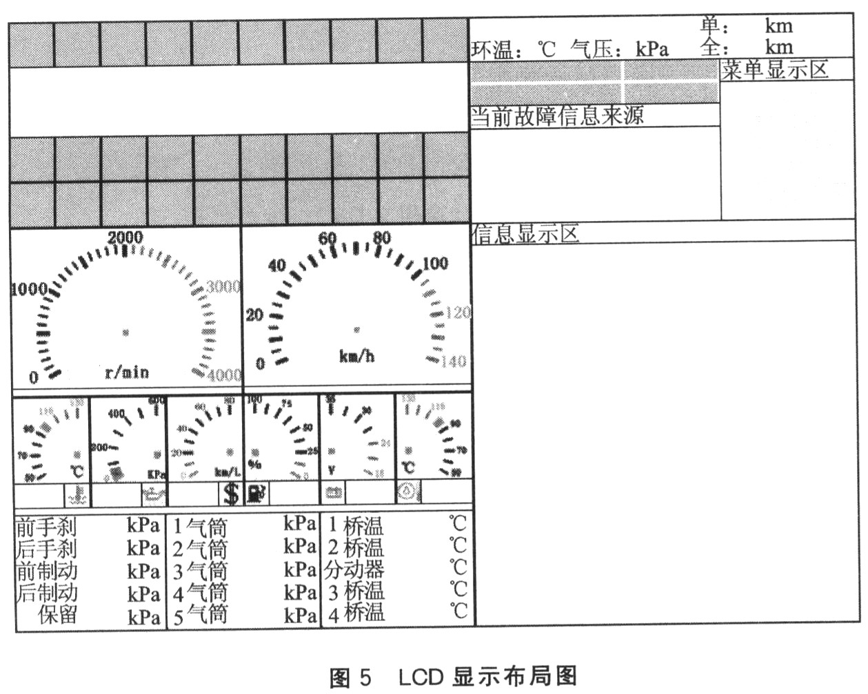
3 Vehicle network information interaction design The liquid crystal display selected for vehicle network information interaction is 8 inch, 640×480 pixels, RS-232 communication, and has 6 passive P9 interface membrane buttons. The display layout is shown in Figure 5. The left half of the figure: the upper part is the red signal indicator and its alarm prompt, and the other is the other color signal indicator: the middle is the instrument analog mode, the table dial pointer or the number mode, the lower is the small instrument alarm prompt; the lower part is Group member data and each group alarm prompt. The right half of the figure: the upper part is the date and time, the ring temperature/air pressure, the single/full mileage, the diagnosis indicator and the DMl source and menu are below; the lower part is the information page, including the basic information, the unprocessed information of each ECU product, DMl and DM2 content, DMl and DM2 download response, DM3 response, DMll response, single mileage clear response and date and time interactive modification.

The functions of the liquid crystal display are: display 8×16 English characters at the specified position, draw lines at the specified position, display the preset bitmap at the specified position, automatically display the date and time, read the date, and read at the specified position according to the specified position. Time, minute, second, set date and time, display/close cursor, turn backlight on/off. When different levels of alarms are made, the two sounds of mitigation or sharpness from the buzzer are used to prompt.
4 vehicle network software design
4.1 Information Interaction ECU
The information interaction ECU selects MC in Freescale's S12X series; 9S12XDP512 is used as the main chip, and the embedded operating system uC/()S-II is used. The slave CPU of the S12X, the interrupt coprocessor XGate, handles the μC/OS-II clock tick interrupt and performs task switching, which improves the real-time performance of the system and reduces the load on the main CPU. XGate is also used to handle serial communication with LCD monitors, communicate with PC serial ports, query valid input of keyboards, and manage alarm buzzers.
The information interaction ECU created five tasks under μC/0S-II: system initial task, indicator task, instrument data task, keyboard related task, J1939 processing task. The initial task of the system turns on the RTI interrupt, power-on self-test, and the date and time display is turned on; the indicator task periodically displays the signal indicator and the red signal indicator alarm prompt, displays the diagnostic indicator and the DMl source, processes the alarm event; and the instrument data task Periodically display the instrument and small instrument alarm prompts according to the selected mode, display group member data and group alarm prompts, display ring temperature/pneumatic pressure and single/full mileage, and handle alarm events; keyboard related tasks are validly input according to buttons and The menu performs paging display switching, system setting modification, etc.; the JI939 processing task periodically traverses the protocol stacks of the two ports for packet sending and receiving, message forwarding, and extraction response.
4.2 Other homemade ECUs
The other self-made ECUs use M (29S12DGl28) in the S12 series of Freescale as the main chip of the ECU. After power-on initialization, the protocol stack is traversed in an infinite loop, responding to the request message, and then collecting data update messages. The program collects sensor information. The application layer message is periodically updated. The program generates a DTC according to the collected signals and data, periodically updates the application layer diagnostic message, and determines whether to send and whether to use the transmission protocol according to the number of DTCs. The program semi-fixed data such as DTC information, Mileage information and so on are stored in the EEPROM, and each time the power is turned on, it is updated in real time after a change.
Conclusion By analyzing the CAN bus function of the ECU product with SAE J1939 CAN interface, several ECUs are customized to integrate the vehicle network based on SAE J1939 protocol. The results of experimental research on the comparison of CAN card and on-board comparison instrument panel in the laboratory show that the integrated vehicle network is stable in operation, rich in information, and can reflect fault diagnosis information in real time, which solves the problem of less information and fault diagnosis of vehicle dashboard. The problem of insufficient real-time.
The slave CPU of the dual-core microcontroller can improve the real-time performance of μC/OS-II and reduce the load of the main CPU.
In addition, the complete communication strategy and mature communication mechanism of the SAEJ1939 protocol enable the protocol to be applied to CAN communication fields similar to other industrial environments, such as train control and factory control, after modifying the application layer and application layer diagnostic definitions.
Our Remove tool are used to insert and extract terminals from connector housings respectively without damaging the terminal or housing, a key criterion for quality wire processing, especially for OEM and aftermarket rework and repair important.
Whether standard or custom-made, our ejection tool kits are designed to perform precision tasks of the highest professional standards, yielding high-quality end products and bringing greater operational efficiency to your business.
The crimp toolare used to clamp the BNC connector jacket and base. It has a hexagonal notch for crimping. Generally, this kind of crimp tool also has the functions of stripping and cutting wires. Three-purpose network cable pliers, multi-functional, strong and durable, is a regular tool in the information age and modern families. Can make RJ45 network cable connector. RJ11 telephone line connector, 4P telephone line connector.
All the functions of the network cable pliers are integrated, and it is convenient to perform operations such as cutting, crimping, and stripping. It is made of iron, suitable for RJ45, RJ11 network cables, hardened and blackened, light and strong.
contact remove tool, contact crimp tool, remove tool
Kunshan SVL Electric Co.,Ltd , https://www.svlelectric.com