The CAN bus was originally a serial digital communication bus designed for the control of automotive vehicle equipment (sensors, actuators). It was successfully developed by German company BOSCH and INTEL in the late 1980s and became an international standard in 1993. ISO11898. Its purpose is to replace conventional direct-conductor signal connections with multipoint, serial digital communication technology, which can save a lot of cabling of on-board equipment. Due to the high reliability of the CAN bus chip, concise protocol, low price, and wide supply, it has also been widely used in industrial measurement and control. However, the harsh industrial environment and electromagnetic interference are serious. How to ensure the reliability of CAN bus communication is particularly important.
First, CAN bus electromagnetic compatibility performance analysisIn the design of electronic products, the electromagnetic compatibility (EMC) performance has a great influence on the system, and it is related to whether it can operate normally and stably. Internationally, the electromagnetic compatibility of electronic products has begun to impose restrictions, and electromagnetic compatibility has become an important indicator of product performance.
Electromagnetic compatibility mainly includes two aspects. One is that the product itself has an adverse electromagnetic interference (EMI) effect on the outside world, which is called electromagnetic interference emission; the other is the degree of sensitivity to external electromagnetic signals, which is called electromagnetic sensitivity. EMS (Electro Magnetic Sensitivity). Sources of interference, coupling paths, and sensitive equipment are three elements of electromagnetic compatibility and are indispensable. The details of electromagnetic compatibility are shown in Figure 2.
There are two kinds of electromagnetic interference signal coupling pathway: conduction and radiation. According to the different coupling results, the interference is divided into common mode interference and differential mode interference. Common mode interference exists between all signal lines (including signal lines, data lines, power lines, etc.) and ground lines, and differential mode interference exists between signal lines.
When using unshielded wires, the electromagnetic compatibility of the physical layer becomes very important. Measures to improve electromagnetic compatibility can be divided into three types: emission protection, absorption protection, and conduction protection.
Launch protection - improve the electromagnetic compatibility of electronic devices
Improving the electromagnetic compatibility of electronic devices is an effective measure to fundamentally improve the electromagnetic compatibility of the system. Printed circuit boards (PCBs) are the core components of electronic devices, and their anti-electromagnetic interference performance and electromagnetic radiation performance are often Interrelated, so you can take the following measures to improve the electromagnetic compatibility of printed circuit boards.
Choose components with good electromagnetic compatibility
Select components with good EMC performance and try to choose the surface mount package. Reasonable layout of the device, put the related devices as close as possible, so that the leads between the components as short as possible. In particular, the clock source crystal of the microcontroller and CAN controller must be placed according to regulations, otherwise it will not start vibration.
Reasonable layout, reduce ground impedance
Reasonable layout includes three aspects. On the one hand, reasonable layout of the components and components, and the arrangement of interconnected components are concentrated as much as possible so that the leads between them are as short as possible. The second aspect is to electronic devices. The internal digital circuit is effectively separated from the analog circuit to prevent signal interference between each other. The third aspect is the rational layout of the ground. Under ideal conditions, all grounds on the board should be equipotential. However, due to the presence of the ground impedance, the ground potential at each point is different, so the ground impedance should be minimized. The most effective way is to make a multi-layer board, in the middle of a layer of ground plane.
Absorption protection - Suppression of induced electromagnetic interference
For external radiation interference, it can be reduced or eliminated by shielding or absorption. Because the method is simple and easy to implement, the shielding effect is good, and the convenience of design is an important measure to improve the electromagnetic compatibility of the system.
Use twisted pair, increase twisted degree, shield ground
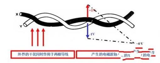
The electric field induces a common-mode voltage in the cable, and the magnetic field can induce both common-mode voltage and differential-mode voltage in the cable. Shielding can reduce the electromagnetic field induced interference to a minimum, and the use of twisted pairs further suppresses the magnetic field induced differential mode voltage. There is a small loop area between the two wires of the twisted pair, and the currents induced on each two adjacent loops of the twisted pair have opposite directions and cancel each other out. The tighter the twisted pair of the twisted pair, the more obvious the effect is, and it is recommended to twist 33 twists per meter. At the same time, in order to reduce the CAN bus crosstalk, the twisted pair should be added to the shielding layer. In order to reduce the electrostatic discharge interference, the entire shielding body needs to be connected to the earth at a single point.
Increase impedance suppression common mode interference
In terms of common-mode interference, differential transmissions in accordance with the ISO 11898-2 standard already provide excellent protection. Within the common-mode range supported by CAN transceivers, the receiver filters out only the voltage difference between the buses. Common mode interference signal. High-energy, inductive induced interference signals may cause interference signals beyond the common-mode range of the transceiver. To suppress this interference signal, a choke coil can be inserted in the input node of the CAN node, as shown in the figure:
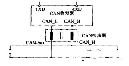
Suppresses inductive induced common-mode interference through choke coils
Separate bus terminals
At high frequencies, the EMC of the CAN network can be improved by separating the bus terminating resistors. At this time, the terminating resistor is divided into two identical large resistors. The two resistors are grounded through a coupling capacitor as shown in the figure. To short-circuit the high-frequency signal to ground without impairing the DC characteristics, it must be ensured that the capacitor is connected to a fixed-level ground.

Conduction Protection - Isolation and Protection of Conducted Interference
Conducted interference mainly occurs in the transient and transient process, such as the transient surge caused by the opening and closing of high-power switches and lightning strikes, which are generally transmitted through the CAN bus cable, resulting in greater electromagnetic hazards. In the transmission route, these transient pulses and surges must be eliminated so that the CAN bus communication can be reliably performed.
TVS Diode TVS
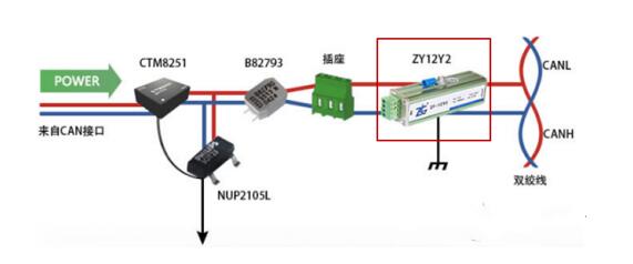
The TVS diode is connected in parallel between the signal line and the signal ground to protect the cable from lightning surges or high voltage surges generated by electrostatic discharge. When the voltage on the TVS exceeds a certain level, the device rapidly turns on, thereby escaping the surge energy and limiting the amplitude of the voltage within a certain range. It is recommended that two TVS tubes be used for two-way protection on each signal line of CANH and CANL.
Isolated Transceiver
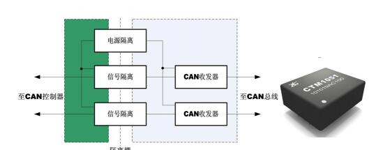
Isolation is the ideal method to solve the problem of conducted interference. It has good electrical insulation and anti-interference ability. Select the isolation transceiver must first consider the transmission delay, such as optocoupler isolation delay up to 25ns or more, magnetic coupling isolation is only 3 ~ 5ns, the delay time of the bus transmission distance and quality will have an impact, it is recommended to use magnetic isolation CTM1051 design interface transceiver circuit.

Optical fiber transmission
Use optical fiber transmission, such as Zhiyuan Electronics' CANHUB-AF1S1, to safely isolate interference.
Signal protector
External dedicated signal protector eliminates interference, such as ZF-12Y2 consumption interference intensity and CANbridge bridge isolation.
Enzyme Skin Care Spray 1SpraySpray test
Any skin. Double sunscreen spray, can effectively prevent the sun's UVA UVB rays infringement, skin sensitive to sunlight especially suitable. Hypoallergenic, preservative-free, clinically tested by dermatologists; fragrance-free, non-alcoholic, non-acne formula, waterproof formula.
Companies registered capital of 35 million yuan, the end of 2014 the total assets of 48.69 million yuan, including fixed assets of 37.52 million yuan. The company's existing cooperation Orange cultivation base 7043.5 acres, the company production base is located in Jiangxi County Tech Industrial Park Chu Tan industrial area, covers an area of 120 acres, it has built a standard plant 9,000 square meters, Nissan 6000 kg Orange enzymes and other liquid enzyme products. Enzyme, known as enzyme, refers to a polymer substance having biocatalytic functionality. In the catalytic reaction system an enzyme, the reactant molecules are known as substrates, enzyme substrates by catalytic conversion to another molecule. Almost all cellular activity of enzymes involved in the process are required to improve efficiency. Similar to other non-biological catalysts, enzymes chemical reactions by lowering the activation energy to accelerate the rate of the reaction, most of the enzyme catalyzed reaction rate can be increased a million times; in fact, the enzyme is to provide an activation energy needs than another low way, so that more particles to have less than the activation energy of the reaction kinetic energy, thus speeding up the reaction rate. Enzyme as a catalyst, in itself is not consumed during the reaction, it does not affect the chemical equilibrium reactions. Positive enzyme catalysis, but also a negative catalytic effect, not only to accelerate the reaction rate, but also to reduce the reaction rate. And other non-living catalysts is different, having a high degree of specificity of enzyme, only a catalytic reaction or produce a particular specific configuration.test
Skin Care Enzyme Spray test,Orange Fragrance Enzyme Spray,Dual Sunscreen Enzyme Spray,Fragrance Free Enzyme SprayFragrance Free Enzyme Spray
Guangdong ganzhou , https://www.tlqcjs.com