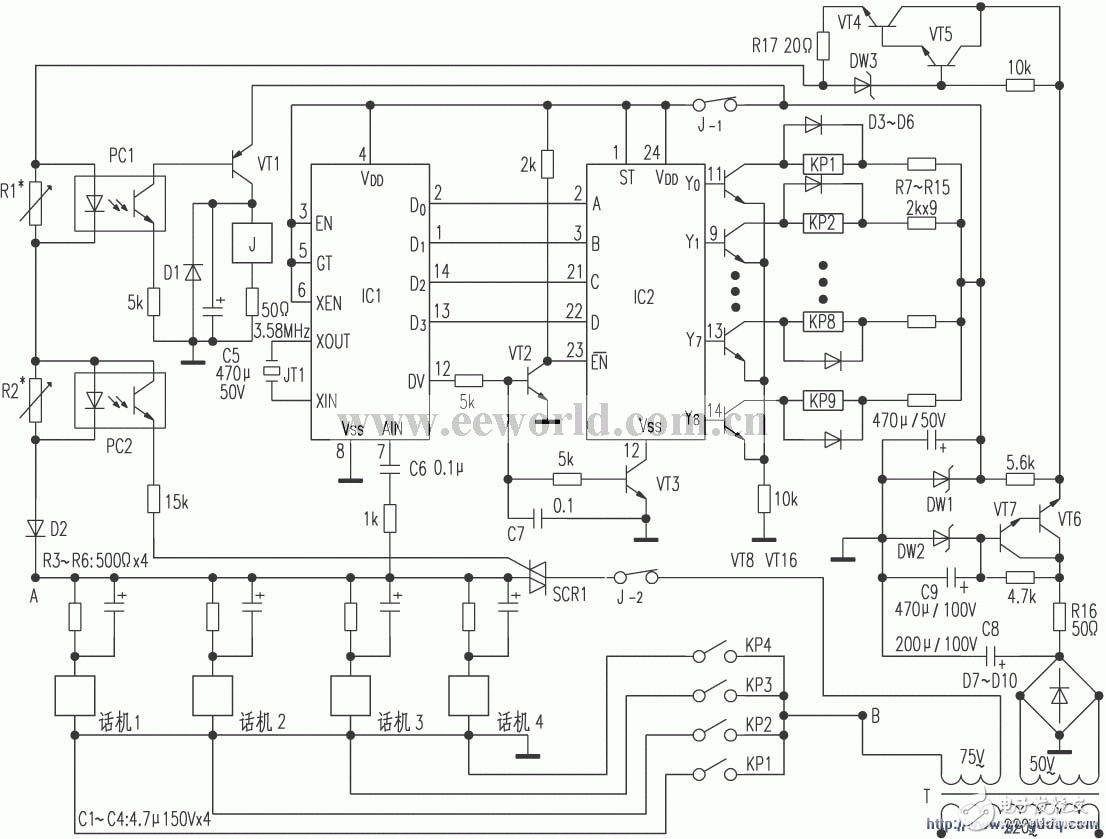
The machine can accommodate 9 telephones, and its capacity can be further increased after expansion (expanding to 16), and the production is simple. After a good trial, it is dedicated to readers with similar needs.
The circuit principle is shown in the attached drawing.

The power source is taken from the city power. Although the power failure affects the normal use, the current power failure probability is very small, which can meet the normal needs of ordinary units. The 220V mains outputs 75V and 50V two sets of low-voltage alternating currents after being transformed. After 50V low-voltage alternating currents are rectified, passively filtered, electronically filtered and stabilized, they get about 48V DC stabilized power supply. VT5, VT4, R17, and DW3 form a high-current constant-current source circuit to limit the maximum current of the main line and prevent damage to the power supply due to short-circuit of the external line. The 75V low-voltage alternating current is the ringing power supply.
For the sake of concise description, only the telephone 1 and 2 are used as examples to illustrate the principles of calling, ringing and talking. If telephone 1 wants to call telephone 2, then telephone 1 will be picked up first, and the external trunk will have a current of about 20 mA on R2. The generated voltage drop (about 0.7V) turns on the optocoupler (PC2). There is a trigger current in the bidirectional silicon controlled (SCR1) control pole. The 75V ringing current is connected to the trunk line through SCR1 and J-2. Press to dial Key 2, the phone's DTMF signal is coupled to IC1 {7} via R and C6, and IC1 is the DTMF decoder (YN9101). XEN is the clock output control terminal, GT is the on-chip timer start terminal, and EN is the decoding output control terminal, both of which are active high.
D0 ~ D3 are binary (8421) code output terminals. When the decoding is successful, the DV pin is at high level. D3 ~ D0 output the 001 code. The VT3 is saturated and turned on. The IC2 {12} pin is grounded. 23} The foot jump goes low. IC2 is the 4 / 16-wire decoder CD4514, A ~ D is the binary code input terminal, corresponding to D0 ~ D3 of YN9101, when the latch control terminal ST = 1, the numbers of A ~ D are latched. Y0 ~ Y15 is the output terminal of decoding. When EN = 1, the output is prohibited. Because EN = 0, the binary code input of terminal D ~ A is 0001, so the output terminal Y1 of the decoding is high level, VT8 is turned on, and drive relay KP2 Pull in. Phone 2 is connected to the ringing voltage via the KP2 contact, and a continuous ringing tone is generated. At this time, if phone 2 is off-hook, the external trunk current doubles (40 mA), and the voltage drop on R1 causes the optocoupler PC1 to conduct, and VT1 With the saturation conduction, the drive relay J attracts. The normally closed contact J-1 is disconnected to cut off the power supply of IC1 and IC2; J-2 is disconnected to cut off the connection between the phone 2 and the ringing voltage, the ringing signal disappears, and the phones 1 and 2 can be directly connected in parallel . If phone 2 does not go off-hook, after phone 1 goes off-hook, there will be no voltage drop on R2, then SCR1 will be terminated due to no trigger current, and phone 2 will also be disconnected from the ringing voltage.
Component selection
In addition to R1, R2, R16, and R17 being 1W, all the other resistors are stalk W, of which R1 and R2 are 100Ω adjustable resistors; PC1 and PC2 are 4N25 photoelectric couplers; J is JTZ-229, KP1 ~ KP8. Choose 4098 type relay; SCR1 chooses T0505 bidirectional thyristor; D1 ~ D10 chooses 1N4000 type diode; DW1 is 12V / 0.5W regulator tube, DW2, DW3 is 48V / 1W regulator tube; VT1 chooses A733 type high reverse For low-voltage power tubes, VT2, VT3, VT5, and VT7 all use 2N5551 high-backpressure low-power tubes. VT4 and VT6 are 3DD15C types, and VT8-VT16 are 3DG130D types. Other components have no special requirements, as long as they are selected according to the mark That's it. Circuit debugging This circuit is relatively simple to debug. Connect the circuit according to the figure, turn on the power after checking the correctness, make any phone off-hook, incorporate a multimeter (AC block) and a 1000kΩ resistor at the A and B terminals, and carefully adjust R2 ( (About 35Ω) until it just has 75V AC indication; either pick two phones, carefully adjust R1 (about 17Ω) until the 75V AC power disappears; repeat the adjustment twice, the circuit can work normally.
Portable power system ,Portable power storage,Portable solar system, Outdoor power station, Portable power station
SHENZHEN CHONDEKUAI TECHNOLOGY CO.LTD , https://www.szfourinone.com