Current real-time signal processors require the ADC to be as close as possible to the video, IF, or RF to obtain as much target information as possible. Therefore, the performance of the ADC directly affects the performance and performance of the entire system, thus enabling the performance test of the ADC. Become very important.
The ADC static test method has been studied for many years. There are standard test methods in the world, but the static test can not reflect the dynamic characteristics of the ADC. Therefore, it is necessary to study the dynamic test method. The dynamic characteristics include many, such as signal-to-noise ratio (SNR), signal. Ratio to noise + distortion (SINAD), total harmonic distortion (THD), spurious free dynamic range (SFDR), two-tone intermodulation distortion (TTIMD), etc. This paper discusses the digital signal method for the signal-to-noise ratio of the ADC. Test, calculate the effective number of bits, and test to prove that increasing the sampling frequency can improve the SNR, which is equivalent to increasing the effective number of ADCs. In this system, the AD9224 is used, which is a 12-bit, 40MSPS, single 5V power supply pipeline type. Low power ADC.

The traditional dynamic test method is to reconstruct the ADC output signal with a high-precision DAC and then analyze it by analog method (as shown in Figure 1). However, such a test method is complicated, has low precision, and has limited indexes for testing. Since the beginning of the year, digital signal processing technology has been used to test the ADC dynamically. The main methods include sine wave fitting method, FFT method and histogram method. However, domestic research in this area has just started.
The test system introduced in this paper is to use the DSP and its simulation system in the digital signal processor developed by the author to collect, store, process and display the data, thus forming a programmable and digital ADC performance test system.
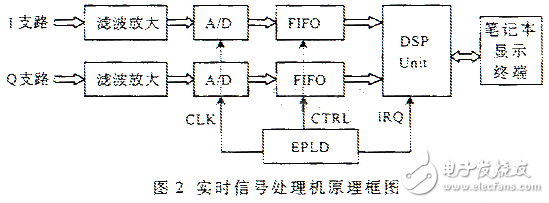
In the signal processor, firstly, two ADCs are used for I and Q orthogonal sampling; then the DSP parallel system is used for FFT operation, modulus and constant false alarm processing; finally, the result is transmitted to the laptop through the parallel port for display. The real-time signal processor block diagram is shown in Figure 2. Among them, the DSP chip is ADSP21060, the main frequency is 40MHz. It can be connected to the PC through the JTAG interface. The online simulation software running DSP on the C machine can control the DSP in real time. Run and display or store the results as data or graphics.
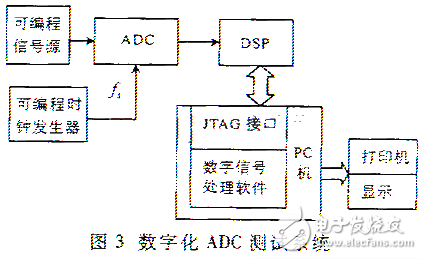
As mentioned earlier, in the past, the ADC was tested using an analog method (see Figure 1), and a high-performance D/A converter was required. Now digital processing is performed using a computer for digital signal processing. The one-way ADC builds the test system, as shown in Figure 3.
In this test system, a single-frequency sinusoidal signal is generated using a signal generator, f = 1.8625 MHz. The sampling frequency fs is generated by an programmable logic device (EPLD), and the sampling clock frequency that can be generated is 3.725 MHz and 7.45 MHz. The sinusoidal signal is sampled in integer multiples (2 times and 4 times). Here, the sinusoidal signal sample data is taken as 256 for processing.

2.1 Signal to noise ratio
For an ideal ADC, the effective value of the noise voltage in the Nyquist bandwidth can be expressed as q/root number 12. q represents the weight of the lowest bit code, ie the quantized voltage of the ADC, which is the amplitude of the input signal. Independent of frequency. For a full-scale sine wave input signal, the theoretical signal-to-noise ratio (SNR) can be expressed as:
SNR=6.02N+1.76dB+10lg(fs/2B) (1)
Where N is the number of bits of the ADC, fs is the sampling frequency, and B is the bandwidth of the analog input signal. The third term on the right side of the above equation indicates that increasing the sampling frequency (oversampling) can improve the signal-to-noise ratio.
2.2 Effective digits
In fact, the error of the ADC is static and dynamic nonlinear error, and the dynamic error becomes larger as the input signal slew rate increases. Therefore, the actual measured signal-to-noise ratio is smaller than the theoretical one. Calculating the effective number of bits (ENOB ) can be obtained from the solution of N of equation (1).
ENOB(N)=6.02N+1.76dB+10lg(fs/2B) (2)

When using DET technology, the noise includes both quantization noise and noise generated by the aliasing of the harmonics outside the Nyquist bandwidth and the signal in the bandwidth during the sampling process. In addition, since the sinusoidal signal is easy to generate and facilitates mathematical analysis, it is evaluated. It is the most commonly used signal when the dynamic performance of the ADC.
3 FFT method to test ADC signal to noise ratio and calculate the effective number of bitsThe FFT is a method of testing the ADC signal-to-noise ratio from the frequency domain. The steps are as follows:
(1) Input the ADC to be tested with a high-precision sine wave. The sine wave frequency f=1.8625MHz, and the sampling frequency is fs=3.725MHz and fs=7.45MHz respectively. The smoked sine wave frequency is less than half of the sampling frequency, ensuring that aliasing does not occur. The ADC output data is recorded in DSP sequence.
(2) Then use DSP to perform FFT operation. When the data record does not contain an integer number of signal periods, a window function is added to suppress spectral leakage. The appropriate window function can be selected to concentrate the signal energy in the main lobe and the energy outside the main lobe. Ignorable.
(3) According to the result of the FFT operation, first calculate the effective value of the signal, then take the fundamental frequency and the appropriate number of samples on both sides to find the square root of their sum of squares. The number of required samples is determined by the resolution of the known ADC. The square root of the sum of the squares of the remaining frequency samples is taken as the effective value of the noise, which includes the quantization noise, the harmonic noise of the ADC, the overshoot noise, and the rounding error of the FFT. With these two effective values, the ADC can be calculated. Signal to noise ratio (SNR):
SNR=20lg(Vs/Vn) (3)
Where Vs represents the effective value of the signal level and Vn represents the effective value of the noise level.
(4) After calculating the signal-to-noise ratio (noise includes high harmonic distortion, stray wave distortion and wideband noise), the effective number of bits of the ADC can be calculated according to formula (2).

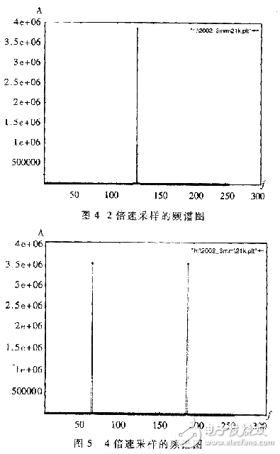
Using the above test system and test parameters, the FFT operation is performed on the data sampled by the ADC, and the calculation is performed according to the above algorithm. The result shows that at fs=2f, SNR=67.6dB, and the effective number of bits is obtained according to formula (2):
ENOB(N)=[SNR(Actual)-1.7dB-10lg(fs/2B)]/6.02
=(67.6-1.7)/6.02=10.95bit
When fs=4f, the sampling frequency is doubled, SNR=70.3dB, which is increased by about 2.7dB. Theoretically, when the sampling rate is doubled, it is obtained by formula (1):
ΔSNR=10lg(fs'/2B)-10lg(fs/2B)=10lg2-10lg1=3dB
That is, the sampling rate is doubled, and the signal-to-noise ratio is increased by 3dB, which is equivalent to an increase of the effective digits of the ADC by half. It can be seen that the actual test data results are basically consistent with the theoretical values. The results of FFT are sampled at the 2x sampling frequency and the 4x sampling frequency. As shown in Figure 4 and Figure 5.
For high-speed ADCs, its dynamic characteristics are especially important, so it is very meaningful to accurately test the dynamic index of the ADC. For real-time signal processors, the large dynamic range and high signal-to-noise ratio of the ADC module unit are especially Importantly, these performances will directly affect subsequent signal processing and detection. Therefore, it is an efficient and high-precision method to test the ADC through software programming using the hardware platform of the real-time signal processor itself.
ZGAR AZ MC Disposable
ZGAR electronic cigarette uses high-tech R&D, food grade disposable pod device and high-quality raw material. All package designs are Original IP. Our designer team is from Hong Kong. We have very high requirements for product quality, flavors taste and packaging design. The E-liquid is imported, materials are food grade, and assembly plant is medical-grade dust-free workshops.
Our products include disposable e-cigarettes, rechargeable e-cigarettes, rechargreable disposable vape pen, and various of flavors of cigarette cartridges. From 600puffs to 5000puffs, ZGAR bar Disposable offer high-tech R&D, E-cigarette improves battery capacity, We offer various of flavors and support customization. And printing designs can be customized. We have our own professional team and competitive quotations for any OEM or ODM works.
We supply OEM rechargeable disposable vape pen,OEM disposable electronic cigarette,ODM disposable vape pen,ODM disposable electronic cigarette,OEM/ODM vape pen e-cigarette,OEM/ODM atomizer device.


Disposable E-cigarette, ODM disposable electronic cigarette, vape pen atomizer , Device E-cig, OEM disposable electronic cigarette
ZGAR INTERNATIONAL(HK)CO., LIMITED , https://www.zgarpods.com