The autopilot technology in science fiction movies makes everyone fascinated. In recent years, with the technological advancement of artificial intelligence, driverless cars have become a reality from our fantasy. Car companies and Internet companies have poured into this new field.
At the end of the two sessions, Baidu Chairman Li Yanhong optimistically said that next year, Baidu and partners launched the L3-class automatic driving production car can be opened at high speed, and in the future can also "eat a hot pot singing songs" on the highway.
Uber's collision accident
However, within a few days of the interval, at 10 o'clock on the evening of March 19, US Eastern Time (Beijing time March 20), a Uber self-driving car traveled northward in Tempe, Arizona, with a distance of 65 kilometers. At the time, he hit a 49-year-old woman who was pushing a bicycle and suddenly crossed the zebra crossing. The woman died after being taken to the hospital. At the time of the incident, although the driver was in the car, the vehicle traveled in the automatic driving mode.
According to a police spokesperson, the deceased Elaine is walking from west to east, and the car has no obvious signs of slowing down. In the statement, the police did not disclose how far the pedestrians were from the test car when crossing the road.
Sylvia Moir, director of the Tempe City Police Department, said: "It is obvious that since she (the deceased) is on the road from a dark place, this accident is inevitable for both people and the autopilot system,"

Moir also said that according to the driver in the car, the pedestrian appeared in front of him like lightning, and he did not react to hear the crash of the accident. "I initially suspect that Uber should not be this. The responsible party of the accident," she said. The speed limit of the accident was 35 mph (about 56 km/h), while the speed of the self-driving car was 38 mph (about 61 km/h), which was actually overspeed.
Although this tragedy may be the responsibility of pedestrians, Uber's autonomous driving technology is still difficult to blame. People want automatic driving to be foolproof, but it does not seem to identify pedestrians crossing the road.
Why is the Sensor not detecting pedestrians? What kind of technical solution is a driverless car? Let's take a look.
Driverless technology
A driverless car is a kind of smart car, which can also be called a wheeled mobile robot. It mainly relies on a computer-based smart pilot in the car to realize driverless driving. A driverless car is a smart car that senses the road environment through an in-vehicle sensing system, automatically plans driving routes, and controls the vehicle to reach a predetermined target.
It integrates many technologies such as automatic control, architecture, artificial intelligence, and visual computing. It is a product of high development of computer science and an important indicator for measuring the scientific research strength and industrial level of a country.
By equip the vehicle with intelligent software and a variety of sensing devices, including on-board sensor radar and camera, to achieve autonomous and safe driving of the vehicle, safely and efficiently reach the destination and achieve the goal of completely eliminating traffic accidents (US National Highway Traffic Safety Administration) ) The classification defines the automation level of the car.
Level 0: driven by the driver;
Level 1: More than one type of automation control (such as adaptive cruise and lane keeping systems);
Level 2: Perform various operational functions with the car as the main body;
Level 3: When the car-based driving is not working, the driver can be instructed to switch to manual driving;
Level 4: Completely unmanned.
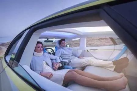
Unmanned technology mainly consists of the following technologies:
1. Lane keeping system
When the road is driving, the system can detect the left and right lane lines. If yaw occurs, the lane keeping system will prompt the driver by vibration, and then automatically correct the direction to assist the vehicle to keep moving in the middle of the road.
2. ACC adaptive cruise system or laser ranging system
Adaptive Cruise Control (ACC) is a car feature that allows the vehicle's cruise control system to adjust to speed to suit traffic conditions.
A radar installed in front of the vehicle is used to detect whether there is a slower vehicle on the road ahead of the vehicle. If there is a slower vehicle, the ACC system will reduce the speed and control the clearance or time gap with the vehicle in front. If the system detects that the vehicle ahead is not on the road of the vehicle, it will speed up the vehicle to return to the previously set speed. This operation enables autonomous deceleration or acceleration without driver intervention. The main way the ACC controls the speed is through engine throttle control and proper braking.
3, night vision system
The night vision system is a car driving assistance system derived from military use. With the help of this auxiliary system, the driver will gain a higher predictive ability during driving at night or in low light. It can provide drivers with more comprehensive and accurate information or early warnings for potential dangers.
4, precise positioning / navigation system
Autonomous vehicles rely on very accurate maps to determine position, as deviations can only occur with GPS technology. Engineers drive to collect traffic data before the car goes on the road, so the car can compare real-time data with recorded data, which helps distinguish pedestrians from roadside objects.
Sensor system for driverless cars
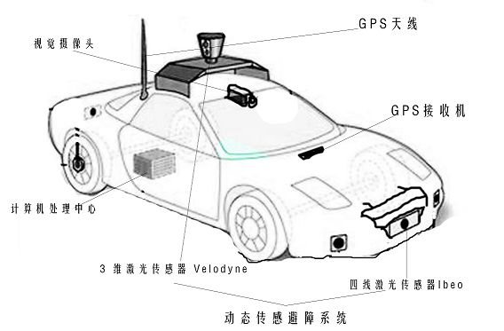
The realization of driverless cars requires a lot of scientific and technical support, and the most important one is the large number of sensor positioning. The core technology is composed of high-precision maps, positioning, sensing, intelligent decision-making and control. There are several key technical modules, including precise GPS positioning and navigation, dynamic sensing obstacle avoidance system, and mechanical vision. Others such as behavior-only planning are not in the sensor category. More design. The sensor system is shown in the figure.
Precise GPS positioning and navigation
Driverless cars have put forward new requirements for GPS positioning accuracy and anti-interference. In the case of unmanned driving, the GPS navigation system must continuously locate the unmanned vehicle. In this process, the GPS navigation system of the driverless car requires that the GPS positioning error does not exceed one body width.
Another challenge facing another problem faced by driverless cars is the need to ensure that they are perfectly navigational. The main technology for navigation is the use of a very wide range of GPS technologies in life. Because GPS has no accumulation error and automatic measurement characteristics, it is very suitable for navigation and positioning of driverless cars.
In order to greatly improve the accuracy of GPS measurement technology, the system uses position differential GPS measurement technology. Compared to traditional GPS technology, differential GPS technology can make a difference between an observation station's observation of two targets, two observation stations' observations of one target, or one station's two measurements of one target. The goal is to eliminate common sources of error, including ionosphere and tropospheric effects.
The position difference principle is one of the simplest differential methods that can be retrofitted and composed of any kind of GPS receiver.
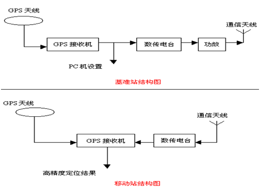
The GPS receiver installed on the base station can observe three satellites and then perform three-dimensional positioning to calculate the coordinates of the base station. Due to orbital errors, clock errors, SA effects, atmospheric effects, multipath effects, and other errors, the calculated coordinates are not the same as the known coordinates of the base station, and there is an error. The base station uses the data link to transmit the corrected number, receives it by the subscriber station, and corrects the coordinates of the user station that it solves.
The corrected user coordinates obtained in the end have eliminated the common errors of the base station and the subscriber station, such as satellite orbit error, SA influence, atmospheric influence, etc., which improves the positioning accuracy. The above prerequisites are the case where the base station and the subscriber station observe the same set of satellites. The position difference method is suitable for the case where the distance between the user and the base station is within 100 km. The principle is shown in the figure.
High-precision car body positioning is a prerequisite for driving a driverless car. With the existing technology, differential GPS technology can be used to accurately position the driverless car, which basically meets the demand.
Dynamic sensing obstacle avoidance system
As a land-based wheeled robot, driverless cars are very similar to ordinary robots, and there are great differences. First of all, as a car, it is necessary to ensure the comfort and safety of the passengers. This requires stricter control of the direction and speed of the vehicle. In addition, it is bulky, especially in complex and crowded traffic environments. Smooth driving, there is a high demand for dynamic information acquisition of obstacles around. Many unmanned vehicle research teams at home and abroad conduct dynamic obstacle detection by analyzing laser sensor data.
Stanford University's autonomous vehicle "Junior" uses a laser sensor to model the motion geometry of the tracking target, and then uses a Bayesian filter to update the state of each target separately; Carnegie Mellon University's "BOSS" from the laser sensor data The obstacle features are extracted, and the dynamic obstacles are detected and tracked by correlating the laser sensor data at different times.
In practical applications, 3D laser sensors have a relatively small delay due to the large amount of data processing workload, which reduces the ability of unmanned vehicles to respond to dynamic obstacles, especially for driverless cars. The obstacles in the front area pose a great threat to its safe driving. The ordinary four-wire laser sensor has a relatively fast data processing speed, but the detection range is small, generally between 100° and 120°. A single sensor also has a low detection accuracy in an outdoor complex environment.
Aiming at these problems, a multi-laser sensor for dynamic obstacle detection is proposed. The 3D laser sensor is used to detect and track obstacles around the driverless car. The Kalman filter is used to track the obstacle motion. And prediction, for the fan-shaped area with high accuracy in front of the driverless car, the confidence distance theory is used to fuse the four-line laser sensor data to determine the motion information of the obstacle, and the detection accuracy of the obstacle motion state is improved. The grid map not only distinguishes the dynamic and static obstacles around the driverless car, but also delays the position of the dynamic obstacle according to the fusion result to eliminate the positional deviation caused by the delay of the sensor processing data. .
The flow chart is shown in the figure, and finally the information is displayed on the human-computer interaction interface.
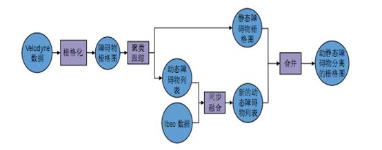
Process structure of dynamic obstacle avoidance system
Firstly, the Veloadyne data is rasterized to obtain an obstacle occupation grid map. Clustering tracking of the grid maps at different moments can obtain the dynamic information of the obstacles, and remove the dynamic obstacles from the grid map. Stored in the list of dynamic obstacles, this raster image that removes the dynamic obstacle occupancy information is also a static obstacle raster map, and then the dynamic obstacle information in the dynamic obstacle list and the unmanned Ibeo acquisition The dynamic obstacle information in the front area of ​​the car is synchronously merged to obtain a new dynamic obstacle list. Finally, the dynamic obstacles in the new list are merged into the static obstacle grid map to obtain a dynamic and static obstacle difference indication. Grid diagram. The obstacle detection module analyzes and processes the data returned by various laser radars, rasterizes the laser radar data, and projects them into a 512*512 grid map to realize the detection of obstacles in the environment.
Finally, the multi-sensor information fusion and environment modeling module fuses the environmental information acquired by different sensors, establishes a road model and finally uses a grid map, which includes: identification information, road information, obstacle information, and Positioning information, etc.
Finally, the obtained environmental information signal is processed to obtain a dynamic raster map indicating the obstacle, so as to achieve the obstacle avoidance effect. The method of obtaining the moving target state by using the Velodyne and Ibeo information is compared with the only method using Velodyne. The way of processing the results, the accuracy and stability of the test results have been greatly improved.
Mechanical vision mechanism
Mechanical vision can also be called environmental perception and is the most important and complex part of driverless cars. The task of the environmental sensing layer of the driverless vehicle is to rationally configure the sensors for different traffic environments, integrate the environmental information acquired by different sensors, and build a model for the complex road environment. The environmental sensing layer of the driverless system is divided into traffic sign recognition, lane line detection and identification, vehicle detection, road edge detection, obstacle detection, multi-sensor information fusion and environment modeling.
The sensor detects the environmental information, but only arranges and stores the detected physical quantities in an orderly manner. At this point, the computer does not know what the physical meaning of the data is mapped to the real environment. Therefore, it is necessary to use the appropriate algorithm to mine the data we are interested in from the detected data and give physical meaning to achieve the purpose of sensing the environment.
For example, when we are driving a vehicle, our eyes look at the front, and we can distinguish the lane line we are currently driving from the environment. In order for the machine to obtain the lane line information, the camera needs to obtain the environment image. The image itself does not have the physical meaning mapped to the real environment. In this case, an image can be found from the image that can be mapped to the real lane line. Its lane line meaning.
There are many sensors for self-driving vehicles to perceive the environment, such as cameras, laser scanners, millimeter wave radars, and ultrasonic radars.
For different sensors, the perceptual algorithm used will be different, which is related to the mechanism of the sensor's perception of the environment. Each sensor's ability to sense the environment and its impact on the environment are also different. For example, the camera has an advantage in object recognition, but the distance information is lacking. The recognition algorithm based on it is also affected by weather and light. Laser scanners and millimeter-wave radars accurately measure the distance of an object, but are far weaker than the camera in recognizing objects. The same sensor will exhibit different characteristics due to different specifications. In order to take advantage of their respective sensors and make up for their shortcomings, sensor information fusion is the future trend. In fact, some component suppliers have done this, such as the camera and millimeter wave radar combined sensing module developed by Delphi has been applied to the production car. Therefore, the system design combines multiple sensing modules to identify various environmental objects.
1. Traffic identification module
The traffic identification module is further divided into traffic sign recognition and traffic signal recognition. Among them, traffic sign recognition is mainly composed of the following parts:
(1) image/video input;
(2) Traffic identification detection;
(3) Identification of traffic signs;
(4) Identification result output;
(5) Experimental database and training sample database.
Traffic signal recognition is mainly composed of the following parts:
(1) image/video input;
(2) Traffic signal detection;
(3) Traffic signal status recognition;
(4) Identification result output.
The block diagram of the traffic identification module is shown in the figure.
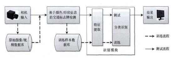
Traffic sign recognition system block diagram

Traffic signal recognition system frame
2. Lane detection and identification module
The lane line detection module obtains the lane line position and direction on the road by detecting and extracting the lane image of the sensor image, and provides the location of the vehicle in the current lane by identifying the lane line, which can help the unmanned vehicle comply with the traffic rules. The autonomous driving of the unmanned vehicle provides guidance to improve the driving stability of the unmanned vehicle. The processing flow of the intelligent lane detection and identification module is mainly:
Preprocessing the acquired image, mainly the smoothing of the image;
To binarize the image, in order to adapt to the unevenness of the illumination distribution, an adaptive threshold binarization method is adopted;
The binarized image is analyzed to find out which road condition the road section belongs to;
Different algorithms are used to detect and identify different road conditions. In the image preprocessing stage, the Gaussian smoothing template is used to smooth the image to remove the interference of image noise. In image binarization, the image is convolved by the mean template of S*S size, the region information of the lane line in the image is extracted, and then the reverse perspective projection transformation is used to identify the lane line through the road condition judgment. The projection principle maps the lane lines to the original image.
3. Vehicle detection module
The vehicle detection module detects the vehicle in the environment by processing the camera image. In order to ensure that any size of the vehicle can be detected in the image, the design uses a sliding window for target detection: in the multi-scale space of the input image, The image is scaled, and then on each scale, by sliding the search window in parallel, subgraphs of different scales and different coordinate positions can be obtained. Secondly, the category of the obtained sub-block diagram is discriminated, the category information of each sub-block diagram is integrated, and the result of the detection is output. The detection uses a region-based Haar feature description operator and an Adaboost cascade classifier.
4. Decision planning layer
The task of the decision-making layer of the driverless vehicle is to generate a global optimal path based on the road network file (RNDF), the task file (MDF) and the positioning information, and rely on the environmental awareness information to reasonably and reasonably reasonably under the constraints of the traffic rules. The driving behavior ultimately results in a safe and travelable path to the control execution system. The decision planning layer is divided into three modules: global planning, behavioral decision making and motion planning.
The global planning module first reads the network file and the task file, traverses all the waypoints in the road network file, generates connectivity between all the waypoints, and then sets the starting point, task point and end point according to the task file to calculate the optimal. The path finally sends the sequence of the route of the optimal path to the behavior decision module.
The behavior decision module divides the behavior of the unmanned vehicle into multiple states and extends to different substates and substates according to different traffic scenarios, mission requirements and environmental characteristics of the vehicle.
The task of the motion planning module is to plan a safe and travelable path in real time according to the local target point and the environment sensing information sent by the behavior decision module, and send the sequence of the track point of the path to the control execution.
Prospects for driverless technology
At present, the realization of unmanned technology is mainly based on laser sensing technology or ultrasonic radar technology. After more than ten years of research and exploration, many organizations and companies have launched their own driverless cars, but basically have shortcomings. It does not achieve the true meaning of "unmanned driving."
The key technologies for solving driverless cars are mainly two aspects, one is the design of the algorithm, and the other is the design of the sensor. The accuracy and response speed of the sensor is directly related to the safety of the driverless car, and safety is the most basic and critical part of the driverless technology. In the future, the direction of unmanned technology should also be to improve the algorithm and select more suitable sensors with higher precision.
In the face of the first unmanned Uber crash, Li Yifan, CEO of Hesai Technology, said that we are not willing to accept the traffic accident itself, but the new technology, which may not necessarily happen. Death accident. From this perspective, the autonomous driving industry is far from mature. We should use awesome hearts to maximize system redundancy with the best performing and most stable sensors, and to comply with the most mature development methods and testing procedures. . All low-cost sensor solutions that try to take shortcuts, human flesh and mouse crowdsourcing are nonsense and crime.
The road to autopilot will be long in the future, and there may be even worse conditions in the future, but these cannot hide the value of autonomous driving for social development.
Modern Physics Experiment Series
Modern physics experiment related equipment for efficient specialized physics laboratory
Modern Physics Experiment Instruments,Optical Instruments,Acousto-Optic Modulator Experimental Device,Optical Spectroscopy Experiment Determinator
Yuheng Optics Co., Ltd.(Changchun) , https://www.yhencoder.com