Recently, the national multi-sector joint document issued a rectification of the electric bicycle industry, requiring that the weight of the electric bicycle should be no more than 40kg, and the maximum speed should not be higher than [1] 20km/h. According to this standard, most electric bicycles in China at present. Unable to meet the standard, and one of the major reasons is that it exists in the power source - lead-acid battery. Due to the small specific energy of such batteries, their volume and weight are large, and lead to lead pollution in the production process, which has now severely restricted the electric bicycle industry.
Lithium battery has not been available for a long time, but because of its large specific energy, small size, light weight, long cycle life, no memory effect, no pollution, etc. [2], it has become the new development direction of electric bicycle energy in the future. At present, foreign electric bicycles have begun to be promoted and used. The working voltage of the lithium battery is in the range of 2.7 to 4.2V, and the series and parallel connection of the multi-cell batteries can be used to meet the requirements of the voltage and power required for the electric bicycle. The use of lithium batteries requires no overcharging, overdischarging, or overcurrent, otherwise the battery life will be reduced and the battery will explode if it is severe. Therefore, it is necessary to design a special protection circuit to manage each battery to ensure the normal charge and discharge of the lithium battery. Completed the research and design of a lithium battery protection circuit for electric bicycles.
1 design requirements
The single lithium battery model is RFE-N18650, as shown in Figure 1, the nominal voltage is 3.6V. The lithium battery pack adopts 4 and 10 string structure, as shown in Figure 2, the nominal voltage is 36V, and the nominal capacity is 9Ah. The protection requirements of the lithium battery pack are: charging upper limit voltage 43V, discharge cutoff voltage 27V. Figure 1 single-cell lithium battery protection circuit should be able to achieve charge and discharge protection for each level of battery, the requirements are as follows: (1) each level of battery charging The voltage is ≤4.3V; (2) The discharge voltage of each battery is ≥2.7V. During the working process of the lithium battery pack, the following functions must be realized:
(1) load short circuit protection;
(2) avoiding the instantaneous starting current of the motor;
(3) The voltage of each stage of the lithium battery pack can maintain a basic balance during charging and discharging.
2 circuit overall implementation
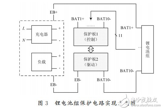
The protection circuit implementation scheme of the lithium battery pack is as shown in FIG. 3, and is composed of two circuit boards. The protection board 1 is used for monitoring the voltage of the lithium battery at each level, and generates a protection signal by the protection IC, for example, prohibiting charging, prohibiting discharge, etc.; the protection board 2 receives the control signal from the protection board 1 and drives the charging and discharging circuits (dark line indication) On and off. EB+/EB- can be connected to a load or charger.

Torque Sensors,Proximity Torque Sensor,Steering Torque Sensor,Power Steering Torque Sensor
Xiaogan Yueneng Electronic Technology Co., Ltd. , https://www.xgsensor.com