The number of cars is increasing, and the traditional traffic light control mode uses timing control. Since the traffic flow is changing at any time, when there is no car passing at this time, the relative car has to wait until the green light in this direction ends to display a red light. Through, the strain performance in time and space is poor, which not only wastes time, but also causes the traffic jam in the opposite direction. In order to overcome the phenomenon that the car-free traffic at the green road of the vehicle-less intersection or the green time of the multi-vehicle intersection is short and the traffic such as traffic jam is wasted, the intelligent traffic light control system appears.
At present, the intelligent traffic light control system has various methods and means for inductive traffic flow, changing the transit time for a predetermined period of time, and intervening by television monitoring information, each having its own characteristics. The design is an intelligent traffic light automatic control system with vehicle flow as the core. By using the ground-sensing coil to detect the traffic flow, the intelligent control of the traffic light at the intersection is realized. With the development of digital cities, the requirements for urban transportation are not only intelligent, but also networked and informationized.
2, system structureThe main controller of the system uses Siemens S7-300 series PLC. The traffic flow detection device adopts the ground-sensing coil based on the principle of electromagnetic induction. The system consists of PLC controller, signal detection device, signal conversion device, emergency button, crossroad traffic light group and The Ethernet interface is composed of several parts, as shown in Figure 1.
Each lane of each intersection is equipped with a ground-sensing coil. After the local sense coil senses the signal passing by the vehicle, the signal is converted into a standard voltage signal of 0~10V through the signal conversion device and input to the PLC. The PLC control system determines the signal. The state, after data processing and calculation to obtain the actual traffic flow data of each intersection, the automatic control system automatically adjusts the traffic state of the signal light at the intersection according to the actual traffic flow of each intersection. At the same time, the system sets an emergency button at each pedestrian intersection, and pressing this button also serves to interfere with the state of the traffic light at the intersection. The Ethernet interface set up by the system lays a foundation for realizing interlocking control of traffic lights between multiple intersections, remote computer monitoring of traffic lights, and network and information management of traffic systems.
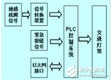
Figure 1 system structure diagram
The Siemens S7-300 series PLC selected by the system mainly includes one CPU314IFM module, one SM332 switch module, one SM334 analog module, one power module and one communication module. The PLC is powered by 24V. The system has a total of 36-point switch input signal, 32-point switch output signal, 6 analog input signals, and 4 analog output signals. It satisfies a 3~4 lane intersection traffic light. Control requirements.
The system controls an actual common intersection traffic light, consisting of main roads and branch roads. There are three lanes in each direction, namely straight lane, left turn lane and right turn lane. Each intersection is equipped with red and yellow. , green straight and green turn direction lights.
3, traffic flow detection 3.1, ground sense coilThe ground sense coil is the most important detection component in the intelligent traffic automatic control system, and is mainly composed of a coil buried under the ground surface and a signal extraction and output device. The technical specifications of the ground coil are determined by the size of the lane and the depth of the buried. The ground coil is mainly composed of four factors: inner diameter, outer diameter, wire diameter and number of turns. Once these four factors are determined, the specification of the coil can be determined. .
When the ground sense coil works in the best condition, the inductance of the coil should be kept between 100uH and 300uH. When the coil inductance is constant, the number of turns of the coil is related to the circumference. The smaller the circumference, the more the number of turns. Refer to Table 1 for the number of coil turns.
Table 1 Coil count reference table
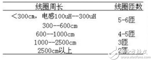
Since various metal materials such as cable pipelines, steel bars, and sewer covers may be buried under the road, these will have a great influence on the actual inductance value of the coil. In actual construction, the inductance tester should be used to actually test the inductance value of the inductive coil. Determine the actual number of turns in the construction, as long as the final inductance of the coil is within a reasonable working range (such as between 100uH-300uH), otherwise the number of turns of the coil should be adjusted.
Under ideal conditions (regardless of the influence of all environmental factors), the ground coil only considers the size (or circumference) and number of turns of the area, regardless of the material of the wire. However, in practical engineering, the mechanical strength of the wire and the anti-aging problem of high and low temperature must be considered. In some environments, the acid and alkali corrosion resistance must also be considered. In the actual project, it is recommended to use Teflon high-temperature multi-strand soft wire of 0.1cm or more.
Taking a 60X60cm simulated intersection traffic model as an example, the scale of the actual intersection is scaled to obtain a lane size of about 3 cm. The inner diameter of the coil selected during the design was 1.8*2.3 cm, the outer diameter was 2.0*2.5 cm, the wire diameter was 0.05 cm, and the number of wires was 180 n.
3.2, signal conversion deviceThe working principle of the ground-sensing coil is based on the principle of the oscillating circuit. The signal conversion device is composed of a signal conversion circuit based on the principle of electromagnetic induction. The conversion circuit mainly consists of two triodes, a common-emitter oscillator and a ground-sensing coil (inductive component). The circuit is composed of a coupling oscillating circuit composed of components such as resistors and capacitors. The circuit principle of the signal conversion device is shown in Fig. 2.
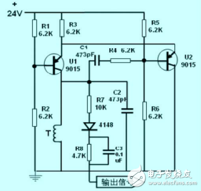
Figure 2 Schematic diagram of the signal conversion device circuit
Ul and U2 form a common emitter oscillator, resistor R3 is the common emitter resistance of the two transistors, and constitutes a positive feedback. The sense coil T acts as an inductive component in the detector resonant circuit and forms an LC resonance together with the oscillation loop. When a large metal object (car) passes, the change of the oscillation frequency due to the change of the space medium (the oscillation frequency increases when there is a metal object) will increase the magnetic flux generated by the unit current in the coil, resulting in the coil inductance. The value changes slightly, and then changes the frequency of the LC resonance. This frequency changes as the input signal when the car passes through the ground-sensing coil, and then passes this signal through the LC filter circuit composed of R7 and C3 to output a stable DC. Voltage, this voltage can be input to the PLC system.
3.3. Method of embedding the ground coilTaking the road in one direction of the intersection as an example, considering that the right-row passage vehicle can pass directly, the ground-sensing coil is buried only on the straight-line passage and the left-row passage. Two ground-sensing coils are embedded in each channel, and the specific buried position is shown in FIG. The first one is close to the parking line to detect the number of vehicles leaving the lane; the latter one is buried at 5~10cm away from the parking line. Generally, it is considered to be buried 1~2 times of the estimated number of normal parking spaces. The number of vehicles entering the lane; the difference between the two is not only the number of vehicles still present in the lane, but also the number of vehicles waiting to pass. This data is also the basis for controlling the state of the traffic lights at the intersection.
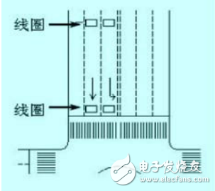
Figure 3 Ground position map of the ground sensor coil
The ground-sensing coil is first buried with a road cutter to cut the groove on the road surface, and 450 chamfering is performed on the four corners to prevent the sharp corner from damaging the coil cable; the slot width is generally 0.4~0.8cm and the depth is 3~5cm. At the same time, a coil to the side of the coil is cut for the coil lead, and the twisted output lead is led out through the lead-out slot. The ground-sensing coil is buried at the same time as the pavement is paved or paved. After the coil is buried, the grooving is sealed with asphalt or soft resin for reinforcement.
When the coil is installed, the solder joint should be avoided as much as possible. If necessary, it must be in good contact and insulated. To avoid electromagnetic interference, the shielded cable is used for the feeder. The shielded cable of the shielded cable is well grounded at the signal converter end. Use twisted pair to prevent two. The feeders of adjacent coils or the mutual interference with the power source 220v.
4, system software designThe system's input and output signals and their I/O address assignments are shown in Table 2.
Table 2 I/O allocation table
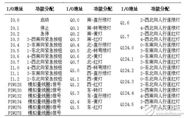
The main control program of the system is designed as a functional module, which consists of a normal operation module, a traffic flow signal intelligent processing module, and an emergency button action module.
Normal operation module: Under normal circumstances, the traffic flow of each intersection is basically equal, and each signal light runs according to the fixed time set by the program; when the traffic volume of a certain intersection changes, the number of vehicles that have detected the intersection reaches the setting. When the value is used, the traffic flow signal intelligent processing subroutine is automatically invoked; when an emergency occurs at a certain intersection, when an emergency is passed, the emergency button of the intersection is pressed, and the program automatically calls the emergency button signal subroutine; after executing the subroutine, The main program automatically returns to continue to retrieve the status of various operating conditions and parameters. The block diagram of the program control is shown in Figure 4.
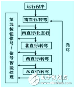
Figure 4 block diagram of the normal operation module
Vehicle traffic signal intelligent processing module: Take one direction as an example, and the timing control is shown in Figure 5.
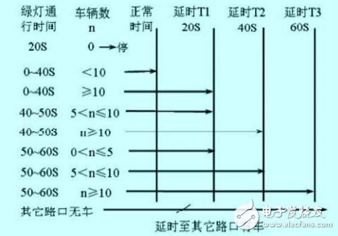
Figure 5 Timing diagram
When the green light of the lane has been illuminated by 20S, and no vehicle has been detected: it means that no vehicle is waiting to pass. If there are no other three intersections, the original normal transit time is maintained; if the other three intersections only have one intersection If you have a car, you will immediately end the green light transit time at the intersection and give way to the intersection with the car.
When the green light of the lane has been illuminated for 40S, it is detected that there is a vehicle "accumulating" in the lane: indicating that there is a vehicle waiting to pass, it is determined according to the actual number of vehicles whether to control according to the normal transit time or delay the passage time, the vehicle The longer the delay, the longer the delay, or the infinite delay, considering the state of the vehicle waiting at other intersections. The number of divisions of the delay period and its specific delay time are set according to the state of each actual intersection.
The program determines the length of the transit time based on the actual traffic volume of each lane detected in different time periods; that is, intelligently processes the transit time of each intersection according to the actual traffic volume of each intersection.
Emergency button action module: The system has an emergency button installed on the sidewalk, which has priority. If an emergency occurs on the sidewalk, just press the emergency button in the direction, and the channel can pass after 5 seconds; the emergency passes After that, it returns to the normal state.
5, system functionIntelligent, automatically adjust the traffic time of each intersection signal according to the traffic volume of each intersection. On the basis of the traditional intersection traffic light control, it overcomes the traditional system of the green road without traffic, or the green time of the multi-vehicle intersection is short. The shortcomings of resource waste such as traffic jams improve the efficiency of traffic and reduce the traffic congestion pressure at intersections.
Humanized, the system has emergency access buttons for pedestrian passages at various intersections, which can flexibly control the system to realize real-time and delayed switching, and has certain priority to facilitate the passage of people in emergency.
Networked, the system's Ethernet interface, can realize the automatic interlock control of traffic lights between multiple intersections, realize remote monitoring of the entire traffic situation, and also lay the foundation for the digitization and informationization of urban traffic. Practicality, the system cost-effective, and easy to install.
6, the conclusionThe intelligent traffic light control system with traffic flow has certain significance in solving urban traffic problems, improving road utilization rate, improving traffic automation level and management level under certain road conditions and certain vehicles. The design has low investment, simple production, convenient installation, stable and reliable hardware, and practical functions, and has practical application value.
The multimedia wiring harness apply to Audio,Video,Radio, LVDs,Flat RCA,USB.
Yacenter has experienced QC to check the products in each process, from developing samples to bulk, to make sure the best quality of goods. Timely communication with customers is so important during our cooperation.
If you can't find the exact product you need in the pictures,please don't go away.Just contact me freely or send your sample and drawing to us.We will reply you as soon as possible.
Electric Fan Wiring Kit,Socket Fan Wiring Harness,Custom Pc Wiring Harness,Multimedia Wiring Harness
Dongguan YAC Electric Co,. LTD. , https://www.yacentercns.com