Many antennas such as half-wave dipole antennas, folded dipole antennas, and loop antennas are balanced-fed. They all have two feed points, and they all have a characteristic: the signal voltage (or current) of the two feed points The phases are opposite to each other. The main feeder cable is often a coaxial cable. The coaxial cable is an unbalanced (asymmetric) feeder. Its inner conductor is the feed point, and the outer conductor is the ground point, which does not participate in the feed. Therefore, even if the characteristic impedance of the antenna is the same as that of the coaxial cable, it cannot be directly connected. Otherwise, the symmetry of the antenna will be destroyed, and the current on the two arms of the antenna will be unequal. This imbalance will change the direction of the antenna. It becomes an asymmetrical pattern, so that the feeder may receive various interference waves and make the feeder mismatch with the antenna. Therefore, when the antenna is connected to the coaxial line, not only the impedance matching but also the balance-unbalance conversion must be considered.
1. λ / 4 balance converter (λ is the wavelength of the signal frequency)
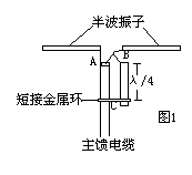
The λ / 4 balance transformation is shown in Figure 1. The input impedance of the half-wave oscillator is 75 ohms.  To balance the load, use a 75-ohm coaxial cable to match it. Although the impedance is matched, the balance is not matched, and a balance converter must be added.
One arm of the half-wave oscillator is connected to the outer conductor of the main feeder (point A in Figure 1), and the other arm is connected to the upper end of the λ / 4 conductor and the inner conductor of the coaxial cable (point B in Figure 1), λ / 4 The lower end of the conductor is connected to the outer conductor of the main feeder through a shorted metal ring (point C in Figure 1). Then the distance between point A and point B is λ / 2, so the signal at point B is just reversed when it is sent to point A, so that the asymmetry of the coaxial line becomes symmetric. Looking from the two points A and B to the short-circuited metal ring is a short-circuit line of λ / 4, and its impedance is infinite, so it will not affect the impedance matching.
2. Asymmetric U-ring balance transformation
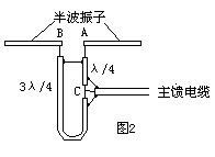
As shown in Figure 2, it consists of two coaxial cables with a characteristic impedance of 75 ohms each.  One section is λ / 4 and the other section is 3λ / 4. The inner conductors of the two coaxial lines are respectively connected to the two arms A and B of the half-wave vibrator, and the other end is connected to the main feed cable at point C. It can be seen that the main feed line is connected to The wave path difference between the two feed points of the vibrator is 3λ / 4-λ / 4 = λ / 2, that is, the signal voltages of the two feed points are equal and the directions are opposite. This ensures balanced feeding.
Impedance matching: Since the half-wave oscillator is balanced, the impedance of each feed point to ground is 75/2 = 37.5 ohms, and the impedance of the feed point A through the 75 ohm cable of λ / 4 to point C is: 75 square meters / 37.5 = 150 ohms, the impedance of feed point B through 3λ / 4 (odd multiple of λ / 4) 75 ohm cable to point C is: 75 square / 37.5 = 150 ohms, then the combined impedance of point C is: 150/2 = 75 Euros. Obviously, the impedance of the main feeder cable is matched.
3. λ / 2 balance converter
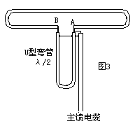
The λ / 2 balanced converter is also called U-shaped balanced converter, as shown in Figure 3, which is equivalent to half  When a wave dipole antenna (with an input impedance of 300 ohms) is connected to a coaxial cable that meets 75 ohms, the impedances of the two do not match, so a U-shaped balun must be installed between them. It can be seen from Figure 3 that the impedance of the feed points A and B to the ground is 300/2 = 150 ohms. The signal is transmitted from the main feed cable to point A and is divided into two paths, which are respectively supplied to the left and right sides of the vibrator. Because the wave path difference between A and B feed points is λ / 2. Therefore, the power supply at the two feed points of A and B is equal and opposite in direction, thus achieving the purpose of balanced conversion.
Looking at the impedance, since the impedances of the two points A and B are both 150 ohms, then when combined together, the impedance of point A should be the parallel value of the two feed points, that is, 150/2 = 75 ohms, so the impedance is also matched.

Follow WeChat

Download Audiophile APP

Follow the audiophile class
related suggestion