Power supply is an indispensable component of various electronic devices. Its performance is directly related to the technical specifications of electronic devices and whether it can work safely and reliably. At present, the commonly used DC stabilized power supply is divided into two categories: linear power supply and switching power supply. Since the key components inside the switching power supply work in the high frequency switching state, the energy consumed by itself is very low, and the switching power supply efficiency can reach 80% to 90%. The general linear regulated power supply has nearly doubled, and has become the mainstream product of the regulated power supply.
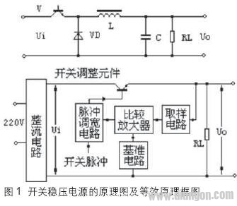
Structure of the switching regulator power supply Figure 1 shows the schematic diagram and equivalent principle block diagram of the switching regulator power supply. It is composed of full-wave rectifier, switching transistor Vi, excitation signal, freewheeling diode VD, energy storage inductor and filter capacitor C. composition. In fact, the core part of the switching regulator is a DC transformer. Here we explain the DC converter and inverter as follows. Inverter, which is a device that converts direct current into alternating current. Inverters are commonly used in backup power supplies that use levels or batteries. A DC converter is a device that converts DC into AC and then converts AC to DC. Such devices are widely used in switching regulated power supplies. A DC converter can be used to convert a DC supply voltage into a variety of DC supply voltages with different polarities and values. 
Advantages and Disadvantages of Switching Regulated Power Supply Switching regulated power supply has low power consumption and high efficiency. In the switching regulator power supply circuit of FIG. 1, the transistor V is alternately operated in the on-off and off-on switching states under the excitation of the excitation signal, and the conversion speed is fast, and the frequency is generally about 50 kHz. In some technologically advanced countries, hundreds or nearly 1000 kHz can be achieved. This makes the power consumption of the switching transistor V small, and the efficiency of the power supply can be greatly improved, and the efficiency can reach 80%.
Small size and light weight. From the block diagram of the switching regulator power supply, it can be clearly seen that there is no cumbersome power frequency transformer. Since the dissipation power on the adjustment tube V is greatly reduced, a large heat sink is omitted. Due to these two reasons, the switching regulator power supply is small in size and light in weight.
Wide voltage range. The output voltage of the regulated power supply from the switch is regulated by the duty cycle of the excitation signal. The change of the input signal voltage can be compensated by frequency modulation or widening. In this way, when the voltage of the power frequency grid changes greatly, it can still ensure a relatively stable output voltage. Therefore, the switching power supply has a wide voltage regulation range and the voltage regulation effect is very good. In addition, methods for changing the duty ratio include pulse width modulation type and frequency modulation type. The switching regulator power supply not only has the advantage of wide voltage regulation range, but also has many methods for realizing voltage regulation. Designers can flexibly select various types of switching power supply according to the requirements of practical applications.
The efficiency of filtering is greatly improved, so that the capacity and volume of the filter capacitor are greatly reduced. The operating frequency of the switching regulator power supply is basically working at 50kHz, which is 1000 times that of the linear regulated power supply. This makes the filtering efficiency after rectification almost 1000 times. Even after half-wave rectification and capacitor filtering, the efficiency is also improved. Increased by 500 times. Under the same ripple output voltage, when the switching regulator is used, the capacity of the filter capacitor is only 1/500~1/1000 of the filter capacitor in the linear regulated power supply. The circuit form is flexible and flexible, and it has self-excited and other excitation modes. There are wide-band and frequency-modulated types, single-ended and double-ended, etc. Designers can use the characteristics of various types of circuits to design different applications. Switching regulated power supply for occasions.
Disadvantages of Switching Regulated Power Supply The disadvantage of switching power supply is that there is a serious switching interference. In the switching regulator power supply, the power adjustment switching transistor V operates in a switching state, and the generated AC voltage and current generate peak interference and resonance interference through other components in the circuit, and if these interferences are not taken to suppress, eliminate, and Shielding will seriously affect the normal operation of the whole machine. In addition, since the switching regulator power supply oscillator is not isolated by the power frequency transformer, these interferences will be stringed into the power frequency grid, causing serious interference to other nearby electronic instruments, equipment and household appliances.
At present, due to the gap between domestic microelectronic technology, production technology of resistive container parts and magnetic material technology and some advanced technology countries, the cost cannot be further reduced, and the reliability is further improved. Therefore, in China's electronic instruments and mechatronics instruments, switching power supplies have not been widely used and used. Especially for high-voltage electrolytic capacitors, high-pressure high-power switch tubes, magnetic core materials for switching transformers, etc., which are not in the power frequency transformer switching power supply, they are still in the research and development stage in China. In some advanced countries, although the switching power supply has a certain development, there are still some problems in practical applications, which can not be very satisfactory. This exposes another disadvantage of the switching regulator power supply, that is, the circuit structure is complicated, the failure rate is high, and the maintenance is troublesome. In this regard, if designers and manufacturers do not pay full attention to it, it will directly affect the promotion and application of switching power supply. Today, the main reason for the difficulty in popularizing and applying switching power supply is that it is difficult to manufacture, has troublesome maintenance and high cost.
Introduction to LDO
LDO is a low-power, low-dropout linear regulator that typically has very low self-noise and a high power supply rejection ratio (PSRR, PowerSupplyRejectionRatio). 
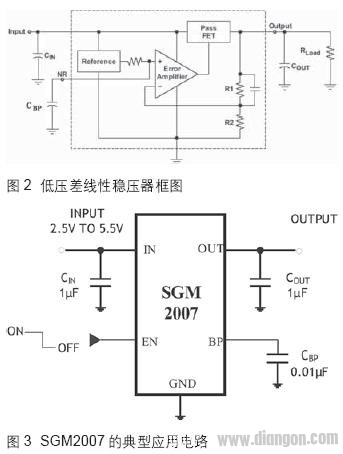
The structure of the LDO low-dropout linear regulator is shown in Figure 2. It mainly includes the startup circuit, the constant current source bias unit, the enable circuit, the adjustment component, the reference source, the error amplifier, the feedback resistor network, and the protection circuit. The basic working principle is: the system is powered on. If the enable pin is at a high level, the circuit starts to start. The constant current source circuit provides a bias to the whole circuit. The reference source voltage is quickly established, and the output rises as the input rises. When the value is specified, the output feedback voltage obtained by the feedback network is also close to the reference voltage value; at this time, the error amplifier amplifies the small error signal between the output feedback voltage and the reference voltage, and then amplifies the output to the output through the adjustment tube, thereby forming a negative Feedback ensures that the output voltage is stable at the specified value. Similarly, if the input voltage changes or the output current changes, this closed loop will keep the output voltage constant, ie Vout=(R1+R2)/R2×Vref. 
The actual low dropout linear regulator also has other functions such as load short circuit protection, over voltage shutdown, thermal shutdown, reverse connection protection and so on.
LDO is used in switching power supply. Most of the low-dropout linear regulators (LDOs) produced by IC design manufacturers are SOT23-5 and SOT23-3, such as SGM2007 and SGM2013 of Shengbang Microelectronics. Figure 3 shows a typical application circuit diagram of SGM2007.
The switching power supply currently on the market uses a switching frequency of 100 kHz made of a bipolar transistor, and a switching frequency of 500 kHz by a MOS-FET. A prominent disadvantage of switching power supplies is the generation of strong EMI. EMI signals have a wide frequency range and a certain range. Conduction and radiation can pollute the electromagnetic environment and cause interference to communication equipment and electronic products. If not handled properly, the switching power supply itself becomes a source of interference. Pay attention to the LDO power supply rejection ratio and power consumption when using the switching power supply as the input VIN of the LDO.
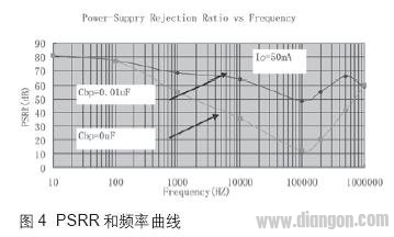
The power supply rejection ratio (PSRR, Powersupplyripplerejectionratio) is an AC parameter that reflects the input ripple rejection capability of the LDO output. The general output and input frequency are the same. The larger the PSRR value, the stronger the LDO ripple capability. The input has little effect on the output. Although the LDO's power supply rejection ratio is very strong, it is very strong in a certain frequency. Generally, the power supply rejection ratio is very poor at 50KHz to 200kHz. Figure 4 shows the PSRR and frequency curve of SGM2007. It is the operating frequency of most switching power supplies. If the load of the LDO and the input and output capacitors are not well matched, it is easy to cause LDO oscillation. This causes instability of the entire LDO power supply system.
Most of the switching power supplies currently on the market are fixed voltage outputs, which are commonly used for 5V output. The most common LDO applications are 3.3V output. When the output of the switching power supply is used as the input of the LDO, There is a large differential pressure of 1.7V. If the LDO current is very large, such as 200mA, then the temperature of the chip will be very high, and the power consumption will be large. When working for a long time at high temperature, it will affect the working life of the chip.
Low-dropout linear regulator power dissipation is primarily a function of input voltage, output voltage, and output current. The following equations can be used to calculate the power consumption in the worst case:
PD=(VINMAX-VOUTMIN)ILMAX. Where: PD = actual power consumption in the worst case, VINMAX = maximum voltage on the VIN pin, VOUTMIN = minimum voltage at the regulator output, ILMAX = maximum (load) output current.
The maximum allowable power dissipation (PDMAX) is a function of maximum ambient temperature (TAMAX), maximum allowable junction temperature (TJMAX) (+125°C), and junction-to-air thermal resistance (qJA). For a 5-lead SOT-23 package mounted on a typical dual-layer FR4 electrolytic copper-plated PCB, the (qJA) is approximately 250°C/Watt.
PDMAX=(TAMAX-TJMAX)/qJA
VINMAX=3.0V+10%, VOUTMIN=2.7V-2.5%, ILOADMAX=40mA, TJMAX=+125°C, TAMAX=+55°C
The actual power consumption is PD=26.7mW, and the maximum allowable power consumption is: PDMAX=280mW.
Conclusion When the switching power supply is used as the input of the low-dropout linear regulator, be sure to pay attention to the ripple of the switching power supply, the influence of the switching frequency on the LDO, and the matching of the LDO load capacitance. Do not exceed the maximum power consumption to affect the stability of the system. .
E-cig as a substitute of tobacco mainly reminds people of its potential benefits for health. Four ingredients contain in the e-liquid : propylene glycol, glycerin vegetable, nicotine and food grade essence. Nevertheless, smoke from cigarette contains carbon monoxide, tar, arsenic, ammonia, and many other cyanide and acetone.
Advantage
- New ceramic self heating element, Uniform heating
- High reduction, Temperaturecan be accurately controlled
- Safety and Health, Worth a product,Natural and realistic taste,Factory Direct Sale
- Using proprietary technology,Quality assurance, trustworthy
- Oil leakage free, compact, pocket-sized, portable and easy to transport
-
So that smokers can smoke addiction, refreshing, to meet the psychological and physiological needs of smokers, and in line with the habit of smokers for many years.
-
Compared with rechargeable e-cigarettes and mechanical e-cigarettes, the price of disposable e-cigarettes is much lower, which is applicable to a wider range of customers than the first two. It is also the absolute truth for ordinary consumer groups to be cheap.
Wax Device Oem,Thc Wax Device Oem,Marijuana Wax Device Oem,High Cost Performance Wax Device
Shenzhen MASON VAP Technology Co., Ltd. , https://www.disposablevapepenfactory.com