In order to meet the application of a micro-power meter and improve safety performance, a design scheme of ultra-low-power lithium battery management system is proposed. The scheme uses a bidirectional high-end micro-current detection circuit, combined with an open circuit voltage and a charge integration algorithm to achieve power detection. Use a button battery instead of a DC/DC step-down circuit to minimize power consumption. The system implements basic protection, remaining power detection, and fault logging. The lithium battery management system was verified on the meter and the results showed good stability and reliability with an average operating current of only 145 μA.
With the rapid development of electronic technology, the application field of instrumentation has been continuously expanded, and battery power has become an important choice. The battery management system is an effective guarantee for battery safety. Most of the current battery management systems are designed for large-capacity battery packs and short-life time applications. The power consumption of such management systems is large, the cycle time of the battery is short, and the power consumption of the management system itself is not low. Used on low power instrumentation fields. A gas remote monitoring instrument, the average system current is only a few milliamperes, and requires continuous operation for more than 6 months at low temperature. In order to meet the application of this project, this paper introduces a design scheme of low temperature intelligent lithium battery management system, for 20Ah. Four strings of 8 and 32 single cells are managed. Basic protection, power metering, charge balancing and fault logging. The experiment verified that the functions of the system were good and met the design requirements.
1. The overall structure of the system
The low-temperature lithium battery management system is mainly composed of basic protection circuit, fuel gauge, equalization circuit, secondary protection, etc., as shown in Figure 1.
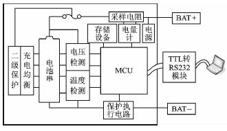
Figure 1 Low-temperature lithium battery management system structure
Based on low power consumption considerations, many low-power devices are used in the design. For example, the processor uses MSP430FG439 low-power single-chip microcomputer; the voltage reference adopts REF3325, the power consumption of the reference power supply is extremely low only 3.9μA; the operational current of the operational amplifier The LT1495 is only 1.5μA; the digital potentiometer uses the AD5165 with quiescent current as low as 50nA. Power management circuits are added to intermittent operating circuits with large operating currents to reduce energy consumption.
The rated voltage of the low-temperature battery pack is 14.8V, which is formed by connecting four groups of batteries. Each group of batteries contains 8 single cells, and the normal working voltage is 2.5~4.2V. The voltage of each group of cells is collected in each collection cycle, and the processor issues an instruction to the protection execution circuit according to the voltage level to perform a corresponding protection action. The equalization circuit is realized by a single chip microcomputer and a triode, instead of the equalization dedicated chip. The system records the maximum value of voltage current and temperature, the battery used time, remaining power and other abnormal information in the storage device. The processor provides a TTL communication interface, and the on-site computer can read the logs in the storage device through a TTLRS232 conversion module. Protection failure occurs during the charging process in order to prevent an abnormality such as an MCU crash. A secondary protection circuit is added. If the voltage exceeds the preset value, the secondary protection circuit will be activated to blow the three-terminal fuse to prevent the accident.
2. Hardware design
2.1 Protection Execution Circuit
The protection execution circuit is the actuator for the protection action, CH is the charge control switch, and DISCH is the discharge control switch. The corresponding protection action is made by controlling CH and DISCH. The circuit diagram is shown in Fig. 2.
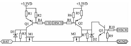
Figure 2 Protection Execution Circuit
CH and DISCH are asserted low during normal operation, and both M1 and M2 are turned on. When a discharge overcurrent or overdischarge occurs, DISCH is set to a high level. At this time, Q2 is turned off and Q3 is turned on, and the charge of the M2 gate capacitor is quickly discharged, so that M2 can be turned off instantaneously to complete the protection. When charging overcurrent or overcharge occurs, set CH to high level and turn off M1. The MOSFET in the circuit uses IRF4310. The MOSFET has an on-resistance of only 7kΩ and a current capacity of 140A.
2.2 Equalization circuit and secondary protection
Fig. 3(a) shows a schematic diagram of a group of cell charging equalization circuits, which are formed by connecting four such units in series. The voltage of the ADV terminal is collected by the single chip microcomputer, and the voltage of the battery cell of the group can be obtained. If the voltage exceeds 4.2V during the charging process, the single-chip control pin BLA is set to a high level. At this time, the group of cells is short-circuited, and the charging current flows through R4 to charge other groups of cells, thereby ensuring that the batteries of each group are charged. It has good consistency after completion.
The secondary protection is irreversible and will only start in very critical situations. The circuit is shown in Figure 3(b). The BQ29411 is a secondary protection chip with a quiescent current of only 2μA. If any group of cells has a voltage exceeding 4.4V, OUT will output a high level, and the three-terminal fuse F3 will start to heat. When the temperature exceeds 139 °C, the fuse will be blown.
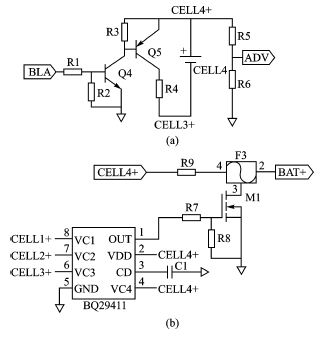
   Figure 3 charge equalization and secondary protection circuit
3. Bidirectional high-end micro current detection circuit
In the small signal detection application of single-supply operation, since the sampling voltage is small, it is often controlled by the power supply rail of the operational amplifier, and it is difficult to complete the detection of small signals. The current high-end detection circuit is adopted in this design, which can get rid of the limitation of small signal detection by single power supply. The high-end detection circuit uses the Linear Technology LT1495 ultra-low power op amp. The circuit diagram is shown in Figure 4.
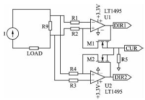
Figure 4 current detection circuit
This circuit can achieve sampling and amplification of bidirectional small current and determine the direction of current. R9 is the sampling resistor. Considering the large current when short circuit, its resistance is generally small. In this scheme, the resistance of R9 is set to 25mΩ. When the battery is in the discharge state, it is assumed that the direction of the loop current composed of the current source, R9 and LOAD is clockwise. At this time, DIR1 is at a low level, DIR2 is at a high level, M1 is turned off, and M2 is turned on. The current flowing through R4 is IR4=R9&TImes; IR9/R4, and the voltage signal at the output of R5 is VCUR=R9&TImes; IR9&TImes; R5/R4. When the battery is in the charging state, the loop current is counterclockwise. At this time, the current signal is amplified by the operational amplifier U1, DIR1 is high level, and DIR2 is low level. Both DIR1 and DIR2 are low when the battery is in an idle state with no current. The lithium battery can be determined to be discharged, charged, or idle by the logic states of DIR1 and DIR2.
4. Power supply design
The power supply design adopts the design scheme of the button battery to power the system, which eliminates the DC/DC and LDO chips and reduces the loss power consumption of the buck chip. The circuit schematic is shown in Figure 5.
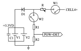
Figure 5 digital power supply schematic
In the figure, R is a digital potentiometer. The AD5165 of Analog Devices is used. Its adjustment range is from 0 to 100kΩ. The quiescent current is only 50nA.V1 and V2 are button batteries. It is selected by Seiko's MS920SE. This model supports maximum current discharge of up to 800μA. . When the acquisition time comes, adjust the resistance of the potentiometer according to the battery voltage value CELL4+, R=(R1+ R2)[(CELL4+)-3.6V)], close the switches W1 and W2 and collect the voltage of POW_DET, thereby determining the button battery. Electricity. If the D1 anode voltage value is less than the charging threshold voltage, indicating that the button battery voltage is too low, turn off W2 and adjust the digital potentiometer to charge the button battery with an appropriate current. The next acquisition cycle comes to re-adjust the digital potentiometer R, close W1 and W2 and collect the voltage of POW_DET, thereby determining whether the button battery is full. If the D1 anode voltage is greater than the charge completion threshold voltage, the button battery is full. Open W1 and W2. Thereby, the charging adjustment control of the button battery is completed. The 3.3V digital power supply is converted to an analog power supply by LC filtering.
5. Software design
The software adopts modular design and mainly includes initialization module, button battery power detection and control module, battery pack status detection and exception processing module, and power estimation module. The software flow chart of the battery pack status detection and exception handling module is given in the paper, as shown in Figure 6.
Each time the system collects the information of the battery pack, it compares the measured value with the historical record value. If it is determined that the current measurement value is the maximum or minimum value, the value is overwritten with the historical value and saved in the storage device. in. Each abnormal condition is also recorded and saved. The PC on the site can read the log in the storage device through the serial port to view the abnormal information.
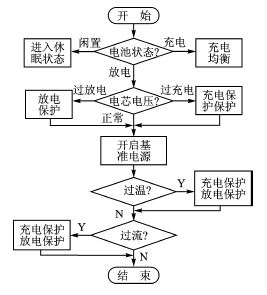
Figure 6 Battery pack status detection and control software flow chart
The SOC estimation uses an estimation method combining open circuit voltage and ampere-hour integral. There are many factors affecting the accuracy of SOC estimation. Temperature, discharge current, cycle number, etc. will bring errors. There is a SOC estimation formula:

Where: SOC is the current amount of electricity, SOC0 is the amount of charge in the initial state, C is the capacity of the battery, and K is the correction factor, which is the empirical value. I is the measured instantaneous current, the charge is negative, and the discharge is positive. In order to obtain an accurate SOC estimate, it is necessary to correct SOC0 periodically or irregularly when applying the ampere-time integration method.
The working current of a gas meter is relatively stable, and the power P=U&TImes; I is a fixed value. It can be seen from the formula that the operating current of the meter increases as the battery voltage decreases. In view of the slow change of the battery voltage, the current sampling circuit in this solution is set to be sampled every 5 minutes to achieve the purpose of reducing power consumption. The nth sampling current in is regarded as the average current in the sampling period, thereby obtaining

The lithium battery management system can estimate the remaining battery life based on the current operating current and SOC conditions.
Conclusion
Some low-power meters have special requirements on battery life. This design is designed for applications with long battery life. A lithium battery management system for low-power meters is designed by hardware and software low-power technology. It can complete the management functions of 4 strings of 8 and 32 low temperature lithium battery packs. Through the operation test of a gas remote monitoring instrument, the lithium battery management system has good performance and the working current is only 145μA, which is far lower than the existing lithium battery intelligent management system.
An Outdoor CPE (Customer Premises Equipment) is a client device used in outdoor environments, typically for wireless network connectivity. It is a device used to transmit Internet signals from a service provider to the user's location.
Outdoor CPE is commonly used to provide broadband access services, especially in remote areas or places without traditional wired network coverage. It can transmit an Internet connection via wireless signals to the building or area where the user is located. Outdoor CPE is typically a highly protected and durable device designed to handle harsh weather conditions in an outdoor environment.
Outdoor Cpes typically include the following main components:
1. Antenna: Outdoor CPE is usually equipped with a high-gain antenna for receiving and sending wireless signals. These antennas can be designed for different frequency bands and wireless standards.
2. Wireless module: Outdoor CPE usually includes a wireless module to handle the transmission and reception of wireless signals. This module usually supports different wireless standards such as Wi-Fi, LTE, 4G, etc.
3. Router function: Outdoor CPE usually has the function of a router, which can distribute the Internet connection to the device where the user is. It can provide IP address allocation, port forwarding, network security and other functions in the local area network.
4. Power supply and battery: Since Outdoor CPE is usually used in outdoor environments, it usually requires a reliable power supply. Some Outdoor Cpes are also equipped with batteries to provide continuous Internet connectivity in the event of a power outage.
The main features and advantages of Outdoor CPE are as follows:
1. High-speed broadband access: Outdoor CPE can provide high-speed broadband access services through wireless signals, so that users can enjoy high-speed Internet connections in places without traditional wired network coverage.
2. Flexibility: Since Outdoor CPE is a wireless connection, it can be used in different locations and environments. Users can place the Outdoor CPE in the best position as needed for optimal signal coverage and performance.
3. Simple installation: Outdoor CPE usually has a simple installation process, and users only need to place the device outdoors and make some basic Settings to start using the Internet connection.
4. Strong anti-interference ability: Outdoor CPE usually has strong anti-interference ability and can provide stable Internet connection under harsh environmental conditions. It can cope with various sources of interference, such as electromagnetic interference, weather conditions and so on.
5. High reliability: Outdoor CPE usually has a high degree of reliability and durability, and can be operated for a long time in a variety of outdoor environments. It usually has waterproof, dustproof, lightning-proof and other functions to cope with different weather conditions.
Outdoor CPE is widely used in a variety of scenarios, especially in rural areas, mountains, islands and other places without traditional cable network coverage. It can provide high-speed broadband access services to residents and enterprises in these areas, helping them to enjoy the convenience of the Internet.
In summary, the Outdoor CPE is a client device for outdoor environments to provide high-speed broadband access services via wireless signals. It is highly reliable, flexible and anti-jamming, and can provide a stable Internet connection in a variety of outdoor environments. It plays an important role in providing broadband access services, especially in places without traditional wired network coverage.
Outdoor Cpe,Router 4G Outdoor,4G Router Bridge Cpe,300Mbps Wifi Ap Outdoor 4G Lte Cpe
Shenzhen MovingComm Technology Co., Ltd. , https://www.movingcommiot.com