Hall current sensor
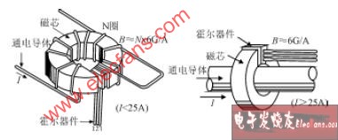
The structure of the Hall current sensor is shown in Figure 35. A ring-shaped magnetically permeable material is used as a magnetic core, which is placed on the wire through which the current to be measured flows, and the magnetic field induced by the current in the wire is gathered to form an air gap on the magnetic core, and a Hall linear device is built in. The current flowing through the wire can be obtained from its Hall output voltage. The sensor shown in Fig. 35 (a) is used to measure a current having a small current intensity, and the sensor shown in Fig. 35 (b) is used to detect a large current.
The actual Hall current sensor has two forms, direct measurement and zero magnetic.

Figure 35 The principle of the Hall current sensor
Direct Measurement Hall Current Sensor The output of the Hall device in Figure 35 (which can be amplified if necessary) is sent to the calibrated display, which directly derives the measured current value from the value of the Hall output voltage. The advantage of this method is that the structure is simple, and the accuracy and linearity of the measurement results are high. It can measure currents of DC, AC and various waveforms. However, its measurement range, bandwidth, etc. are subject to certain restrictions. In this application, the Hall device is a magnetic field detector that detects the magnetic induction in the core air gap. After the current increases, the core may reach saturation; as the frequency increases, the eddy current loss and hysteresis loss in the core will also increase. These will have an impact on the measurement accuracy. Of course, some improvement measures can be taken to reduce these effects, such as selecting a magnetic core material with high saturation magnetic induction; making a multi-layer magnetic core; using multiple Hall elements for detection, and the like.
Such Hall current sensors are also relatively inexpensive and easy to use, and have been widely used, and have been produced by many manufacturers at home and abroad.
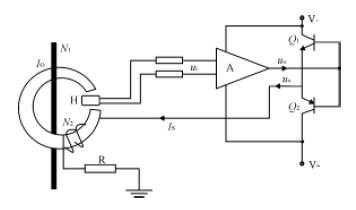
The zero-magnetic (also known as magnetic-balanced or feedback-compensated) Hall current sensor is shown in Figure 36. The output voltage of the Hall device is amplified, and after current amplification, the current is passed through the compensation coil. The magnetic field generated by the compensation coil is opposite to the direction of the magnetic field generated by the current to be measured. If the condition IoN1=IsN2 is satisfied, the magnetic flux in the magnetic core is 0, and the following formula holds: Io=Is(N2/N1)(5)
Where, I1 is the current to be measured, that is, the current in the primary winding in the core, N1 is the number of turns of the primary winding, I2 is the current in the compensation winding, and N2 is the number of turns of the compensation winding. It can be seen from the equation (5) that when the magnetic balance is reached, Io can be obtained from Is and the turns ratio N2/N1.

Figure 36 Hall Zero Flux Current Sensor

Figure 37 Hall current sensor in relay protection and measurement (H is Hall current sensor)
This balancing process is automatically established and is a dynamic balance. The time required to establish a balance is extremely short. When balanced, the Hall device is in a zero flux state. The magnetic induction in the core is extremely low (ideally should be 0), does not saturate the core, and does not cause large hysteresis losses and eddy current losses. By properly selecting the core material and the line components, a zero-flux current sensor with excellent performance can be made.
A Hall voltage sensor can be constructed by connecting an appropriate load resistor to the output circuit of the Hall current sensor.
Hall current sensors are characterized by "potential-free" detection of current. That is, the measurement circuit can realize current detection without having to access the circuit under test, and they are coupled by a magnetic field. Therefore, the input and output circuits of the detection circuit are completely electrically isolated. During the detection process, the state of the circuit under test is not affected by the detection circuit, and the detection circuit is not affected by the circuit to be inspected.
The Hall current sensor can sense currents from DC to 100kHz (through careful design and fabrication, even up to MHz) with response times as short as 1μs.
Due to these advantages, Hall current sensors have been widely used. 3 æµ2æµ12 Hall current sensor application
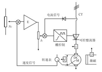
3æµ2 æµ12æµ1 Relay protection and measurement As shown in Figure 37, the secondary current from the current transformer of the high-voltage three-phase transmission line passes through three Hall current sensors H (only one of the B phases is shown in the figure) Only), proportionally converted to millivolts voltage output, and then amplified by the operational amplifier and active filtered to obtain the required voltage signal, sent to the microcomputer for measurement or processing. Undistorted, time-delayed signal conversion is conveniently achieved using Hall current sensors. 3æµ2 æµ12æµ2 Application in DC automatic control speed control system In the DC automatic control speed control system, the Hall current voltage sensor is used to replace the current transformer, which not only has good dynamic response, but also realizes the most rotor current. Good control and overload protection of the thyristor, the application circuit shown in Figure 38.

Figure 3 Application in DC Control
Hall element and its application
SMD Tact Switch TSTP454550,smt tact switch TSTP454550,kfc tact switch TSTP454550
Wenzhou Hesheng Electronic Co., Ltd. , https://www.heshengelec.com