Discrete component unsteady multi-resonant circuit The unsteady multivibrator is a simple oscillator circuit. It can generate a rectangular pulse continuously and periodically without the need of an external excitation signal. The pulse is composed of a fundamental wave and multiple harmonics, and is therefore called a multivibrator circuit. The multivibrator may be composed of a triode or a 555 or a general-purpose gate circuit. A multivibrator consisting of two triodes, commonly called a triode unsteady multivibrator.
In this example we will use a triode to make a multivibrator and use it to drive two different colored LEDs. When the production is complete, we can see that the two LEDs are lit alternately, and we can adjust the parameters of the circuit to adjust the lighting time of the LED.
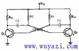
Circuit diagram of the triode multivibrator: 
Below we will briefly analyze the working principle of this circuit:
The figure above shows a self-excited or unsteady multivibrator circuit for a junction transistor. It basically consists of a two-stage RC-coupled amplifier, where the output of each stage is coupled to the input of another stage. The levels are alternately turned on and off, and only one level is conductive at a time.
From the circuit structure, the self-micro-multivibrator is similar to the two-stage R c sinusoidal oscillator, but it is actually different. The sinusoidal oscillator will not enter the cutoff state. The multivibrator will enter the cutoff state. This is controlled by means of a longer time constant of the R c coupling network. Although alternating in time, both stages produce a rectangular wave output. So the output of the multivibrator can be taken from any level.
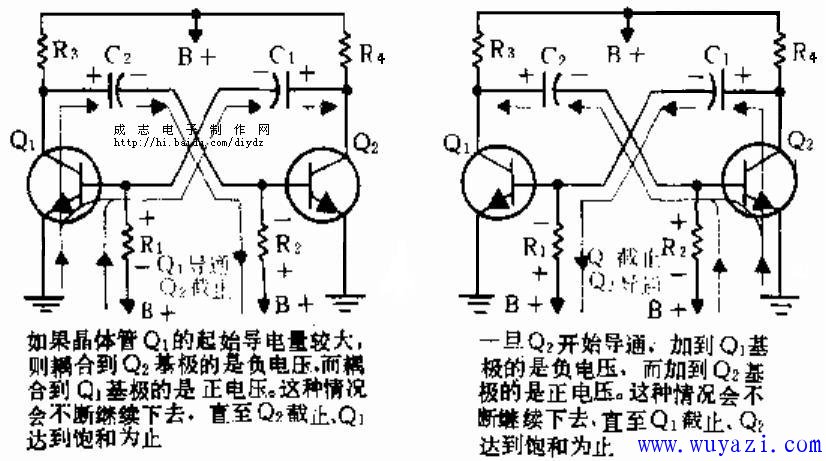
When the circuit is powered up, Vcc is applied to the circuit. Since both transistors are forward biased, they are in a conducting state. In addition, the coupling capacitors C1 and C2 are charged to a voltage close to Vcc. The path of charging is from the ground point through the base of the transistor and through the capacitor to the Vcc supply. Some of the charging current is passed through R1 and R2, causing a positive voltage to be applied to the base, which causes the transistor to conduct more, thus lowering the collector voltage of the two stages.
The two transistors will not be identical, so even if the two stages use the same type of transistor and use the same component values, one transistor will be slightly larger than the other.
Assuming that the conductivity of Ql is slightly larger, due to the large current of Q1, its collector voltage drop is faster than that of Q2. As a result, the voltage across the capacitor C2 discharged through the resistor R2 to the base of Q2 is greater than the negative voltage of the base coupled to the base of Q1 by C1 and R1. This reduces the amount of conductivity of Q2, and its collector voltage increases accordingly. 
The voltage at which the collector of Q2 rises is coupled back to the base of Q1 as a positive voltage. Thus, Q1 conducts more, causing its collector voltage to drop further, since C2 is still discharging. Therefore, the base voltage of Q2 is driven to increase negatively. This process continues until the final Q2 cutoff, while Ql is turned on in saturation. At this time, the capacitor C2 still discharges the ground point through the resistor R. The Q2 stage remains off until C2 is fully discharged such that the base voltage of Q2 exceeds the cutoff value. Then Q2 begins to conduct, which begins the second half of the multivibrator.
Since Q2 begins to conduct, its collector voltage begins to drop, causing capacitor C1 to begin discharging through resistor R1, thus adding a negative voltage to the base set of Q1. The current conducted by Q1 is thus reduced and causes the Q1 collector voltage to rise. This is a positive voltage coupled to the base of Q2, so Q2 conducts more current. Just like the work in the first half of the week, this is a positive feedback, and continues until the Q1 cutoff, Q2 is turned on in saturation. Q2 remains in the off state until C1 is fully discharged and Ql begins to leave the off state. At this point, the complete cycle begins again.
The length of the first-level conduction time depends on the time of the other level. That is, it depends on the time constant RC of C1R1 and C2R2. The smaller the time constant, the faster the conversion effect, so the output frequency of the multivibrator is higher. For the above circuit, the time constants of the two RC networks are the same, and the on and off periods of the two transistors are equal, so it is called a symmetric self-excited multivibrator.
Of course, we can also adjust the C1R1 and C2R2 to different, so that the conduction time of the two transistors is different.
After understanding the basic principle of the multivibrator, we can use this circuit to control the alternate flashing of the two LEDs.
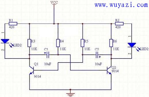
Design and fabrication of alternating stroboscopic LED lamps We can drive the collectors of Q1 and Q2 as the output of the oscillator to drive two LEDs. The specific circuit is as follows: 
R1 and R2 are the current limiting resistors of the light-emitting diodes D1 and D2, respectively, here 420 ohms. The smaller the value, the brighter the LED will be. R3 and R3 take the value 11K.
The time during which each lamp is lit can be obtained by calculating the on-time for R4*C1, R5*C2 using the formula T=0.693*R*C. The reader can take different values ​​to get different flickering frequencies, and the lighting time on both sides can be different.
This circuit is relatively simple. After confirming that the connection is correct, the power can generally start up. It should be noted that the polarity of the capacitors C1 and C2 cannot be reversed. If it is reversed, it will damage the capacitor.
Germany type 16A 250V~, IP20, Class I, non-rewirable, single-way socket outlet complies ,with shutter, with a non-rewirable plug, with cord H05VV-F 3G1,0-1,5mm 2 (max length be 2m for 1,0mm 2 and 30m for 1,5mm2 ).
16A 250V~, IP20, Class II, non-rewirable, with single way socket-outlet with shutter, with a non-rewirable plug, with flexible cord H05VV-F (with or without fabric braided cover) 2G1,0-1,5mm 2 (Max. 2m for 1,0mm 2 in length and Max.30m for 1,5mm 2 ).
Germany Extension Cord,Power Strip Extension Cord,European Extension,Eu European Power Extension Cord
CIXI KYFEN ELECTRONICS CO.,LTD, , https://www.kyfengroup.com