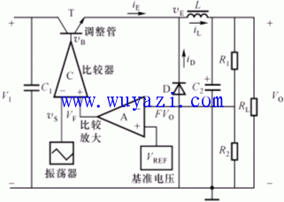
The basic regulated power supply belongs to the linear regulator circuit, and the adjustment tube in the circuit works in the amplification area. The adjustment tube of the switching regulator circuit operates in the switching state, and generally operates in the saturation region and the cutoff region at a modulation frequency of (10 to 100) kHz. When the tube is turned off, although the voltage is high, the current is zero; when the tube is saturated, although the current is large, the tube pressure drop is small. Usually only consider the high frequency switching losses of the tube. Therefore, the power consumption of the tube is small, and its efficiency is high (80% to 90% or more).
Series switching power supply: 
The circuit consists of three parts: switch adjustment tube (T), free-wheel filter section D and L-C2, and control links (A, R1-R2, VREF). The function of the freewheeling filter is to smooth the switching pulse voltage waveform output from the regulating tube and become a smooth DC output voltage.
Since this voltage is unstable, it is necessary to pass the output sampling, feedback control adjusts the saturation and cut-off time of the tube, and the output voltage is automatically adjusted. 
Let the comparison amplifier output voltage VF < 0. During the triangular wave signal voltage VS>VF, the comparator outputs a negative potential, VB=-Vom. On the contrary, during VS<VF, VB=+Vom, thereby obtaining VB as a rectangular pulse. When the VF fluctuates, the pulse width ton and the duty ratio q (=ton/T) of the VB waveform change. 
When VB=+Vom, the adjustment tube T is saturated, iL=iE, and stores energy in L. The emitter potential of T is VE=VI-VCES≈VI, and when VB=-Vom, the adjustment tube T is turned off, iE=0. At this time, the inductor L releases the energy storage, and its back-potential causes the diode D to conduct, iL=iD, so the current continues to flow through the load, and the name of the freewheeling diode D is obtained therefrom. At this time, the emitter potential of T is VE=-VD≈0. If the DC resistance in L is ignored, the output DC voltage Vo is the average component of VE. 
, q is the emitter pulse duty cycle.
When VI is constant, Vo is proportional to the duty cycle q. When the parameters L and C of the filter are not large enough, the output voltage will exhibit a certain ripple whose fundamental frequency is the same as the frequency of the triangular wave. 
The voltage regulation process is as follows: When the output DC voltage Vo drops, the sampling voltage FVo decreases, so |VF| decreases. As can be seen from the diagram (a), at this time, the conduction time ton of the adjustment tube T is increased, so the duty ratio q of the VB waveform is increased, which causes Vo to increase, thereby making up for the reduction of Vo. When Vo increases for some reason, the result of the feedback control will reduce the duty cycle q of the VB waveform, thereby causing Vo to drop to compensate for the increase in Vo. It can be seen that the voltage regulation process of the switching power supply is realized by changing the pulse width (or duty ratio) of the VB waveform, and thus is called a pulse width modulation (PWM) type switching power supply.
51V Battery Pack,Portable Battery Box,Portable Battery Bank,Ac Battery Pack
Zhejiang Casnovo Materials Co., Ltd. , https://www.casnovonewenergy.com