When sampling color TV images, two sampling methods can be used. One is to use the same sampling frequency to sample the brightness signal and color difference signal of the image, and the other is to use different sampling frequencies for the brightness signal and color difference signal. If the sampling frequency used for the color difference signal is lower than the sampling frequency used for the luminance signal, such sampling is called image subsampling.
The basic basis of sub-sampling is the two characteristics of the human visual system. One is that the human eye is less sensitive to chrominance signals than to luminance signals. This feature can be used to remove some of the signals that express color in the image. It is unnoticeable. Second, the human eye has a certain limit to the resolution of image details. This feature can be used to remove high-frequency signals in the image and make it difficult for people to perceive. Subsampling uses this feature to compress the color TV signal.
The following sub-sampling formats are currently used.
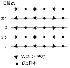
(1) 4: 4: 4 YCbCr format
This sampling format is not a sub-sampling format. It refers to taking 4 luminance Y samples, 4 red difference Cr samples, and 4 blue difference Cb samples at every 4 consecutive sampling points on each scan line. This is equivalent to Each pixel is represented by 3 samples (Figure 07-04-3, 625 scan line system). For consumer and computer applications, the accuracy of each sample of each component is 8 bits; for editorial applications, the accuracy of each sample of each component is 10 bits. Therefore, each pixel needs 24 bits or 30 bits.

Figure 07-04-3 4: 4: 4 sub-sampling format
(2) 4: 2: 2 YCbCr format
This sub-sampling format refers to taking 4 luminance Y samples, 2 red difference Cr samples and 2 blue difference Cb samples every 4 consecutive sampling points on each scan line, and each pixel is represented by 2 samples on average ( Figure 07-04-4, 625 scan line system). For consumer and computer applications, the accuracy of each sample of each component is 8 bits; for editorial applications, the accuracy of each sample of each component is 10 bits. Therefore, each pixel needs 16 bits or 20 bits. In the frame buffer, each sample requires 16 bits or 20 bits. When displaying pixels, for Y samples without Cr and Cb, use the adjacent Cr and Cb samples to calculate the calculated Cr and Cb samples.

Figure 07-04-4 4: 2: 2 sub-sampling format
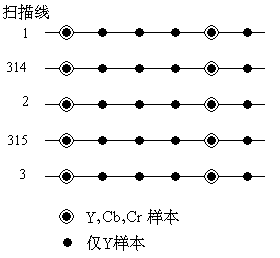
(3) 4: 1: 1 YCbCr format
This sub-sampling format refers to taking 4 luminance Y samples, 1 red difference Cr sample and 1 blue difference Cb sample every 4 consecutive sampling points on each scanning line, and each pixel is represented by an average of 1.5 samples ( Figure 07-04-5, 625 scan line system). When displaying pixels, for Y samples without Cr and Cb, use the adjacent Cr and Cb samples to calculate the Cr and Cb samples of the Y sample. This is the format used on digital television cassettes (DVC, digital video cassette).

Figure 07-04-5 4: 1: 1 sub-sampling format
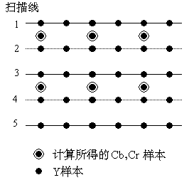
(4) 4: 2: 0 YCbCr format
This sub-sampling format refers to taking 2 luminance Y samples, 1 red difference Cr sample, and 1 blue difference Cb sample at every 2 consecutive sampling points in the horizontal and vertical directions, with an average of 1.5 samples per pixel . In actual implementation, there are two slightly different forms.
(1) H.261, H.263 and MPEG-1
In the sub-sampling format used by H.261, H.263 and MPEG-1, there are 2 samples in the horizontal direction and 2 Y samples in the vertical direction, a total of 4 samples, one Cb sample and one Cr sample The sampling has an offset of half a pixel in the horizontal direction (Figure 07-04-6, 625 scan line system). If the accuracy of each sample of each component is 8 bits, 12 bits are required for each sample in the frame buffer.

Figure 07-04-6 4: 2: 0 sub-sampling format used by MPEG-1 etc.
(2) MPEG-2
In the sub-sampling format used by MPEG-2, there are 2 samples in the horizontal direction and 2 Y samples in the vertical direction, a total of 4 samples have 1 Cb sample and 1 Cr sample, but the sub-sampling does not have half in the horizontal direction Pixel shift (Figure 07-04-7, 625 scan line system).

Figure 07-04-7 MPEG-2 spatial sample position
Figure 07-04-8 illustrates the above 4 seed sampling formats with a graphical method.

Figure 07-04-8 Color image YCbCr sample space position
CL-2H Copper Connecting Terminals
Our company specializes in the production and sales of all kinds of terminals, copper terminals, nose wire ears, cold pressed terminals, copper joints, but also according to customer requirements for customization and production, our raw materials are produced and sold by ourselves, we have their own raw materials processing plant, high purity T2 copper, quality and quantity, come to me to order it!
CL-2H Copper Connecting Terminals
Taixing Longyi Terminals Co.,Ltd. , https://www.longyicopperlugs.com